Reference
WFM700 Series Waveform Monitors User Manual
3-11
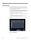
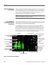
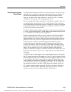
The Surround Sound display indicates the audio level balance among the left (L),
right (R), left-surround (Ls), and right-surround (Rs) channels as cyan lines on
the ruled scales radiating from the center. The scale has tic marks at 10 dB
intervals. An additional tic mark indicates the --18 dB level. The --18 dB and
--20 dB levels are typically used for aligning audio levels
.
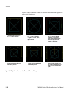
The cyan polygon formed by connecting the level indicator endpoints shows the
total sound volume formed by the L, R, Ls, and Rs channels. This connecting
line will bend away from the center if the two signals have a positive correlation,
will bend towards the center if the signals have a negative correlation, and will
not bend if the signals are uncorrelated.
The Center Volume indicator displays the sound volume of the center channel as
a vertical yellow bar between the L and R channels, and connects the ends of the
L, C, and R audio level indicators with straight lines.
Phantom Sound Indicators (PSI), located on each side of the Surround Sound
display, indicate the location of potential phantom sound sources formed by
adjacent channels. The white tic marks on these moving bar indicators show the
phantom source locations. The bar length indicates the correlation between the
adjacent channels. A short-to-medium length green bar indicates positive
correlation between the channels, forming a localized phantom sound source
located at the white tic mark. The bar grows to full length and changes color to
yellow as the correlation moves to zero, indicating a wide, non-localized sound
image. The bar changes color to red for adjacent channels with significant
negative correlation. For negative correlations, the ends of the PSI for the L and
R channels will continue to grow at a 45 _ angle while the other PSIs remain at
full length.
A fifth PSI at the top of the display shows potential phantom sources formed by
the LC channel pair and the CR channel pair. If the L, R, and C channels all have
the same signal level, the white tic mark on the bar will appear directly above the
C level indicator. The white tic mark will move right or left depending on the
relative balance between the three channels. A short bar to the left of the white
tic mark indicates a positive correlation between L and C. The bar will grow as
the correlation decreases. Like the L--R PSI, the bar will continue to grow at a
45 _ angle for negative signal correlations. The bar to the right of the white tic
mark behaves in the same way, depending on the C--R correlation. This PSI
indicator uses the same color coding as the other PSI indicators.
Interpreting the Surround
Sound Display
Test Equipment Depot - 800.517.8431 - 99 Washington Street Melrose, MA 02176 - FAX 781.665.0780 - TestEquipmentDepot.com


