TMS320C6712D
FLOATINGĆPOINT DIGITAL SIGNAL PROCESSOR
SPRS293A − OCTOBER 2005 − REVISED NOVEMBER 2005
20
POST OFFICE BOX 1443 • HOUSTON, TEXAS 77251−1443
DEVICE CONFIGURATIONS
On the device, bootmode and certain device configurations/peripheral selections are determined at device
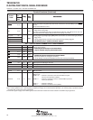
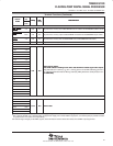
reset. Other device configurations (e.g., EMIF input clock source) are software-configurable via the device
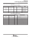
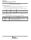
configurations register (DEVCFG) [address location 0x019C0200] after device reset.
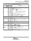
device configurations at device reset
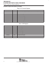
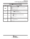
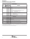
Table 14 describes the device configuration pins, which are set up via internal or external pullup/pulldown
resistors through the LENDIAN, EMIFBE
, BOOTMODE[1:0], and CLKMODE0 pins. These configuration pins
must be in the desired state until reset is released. For more details on these device configuration pins, see the
Terminal Functions table of this data sheet.
Note: If a configuration pin must be routed out from the device, the internal pullup/pulldown (IPU/IPD) resistor
should not be relied upon; TI recommends the use of an external pullup/pulldown resistor.


