


TMS320C6712D
FLOATINGĆPOINT DIGITAL SIGNAL PROCESSOR
SPRS293A − OCTOBER 2005 − REVISED NOVEMBER 2005
25
POST OFFICE BOX 1443 • HOUSTON, TEXAS 77251−1443
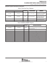
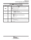
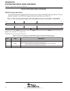
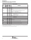
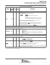
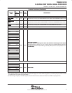
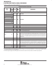
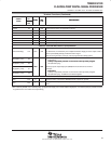
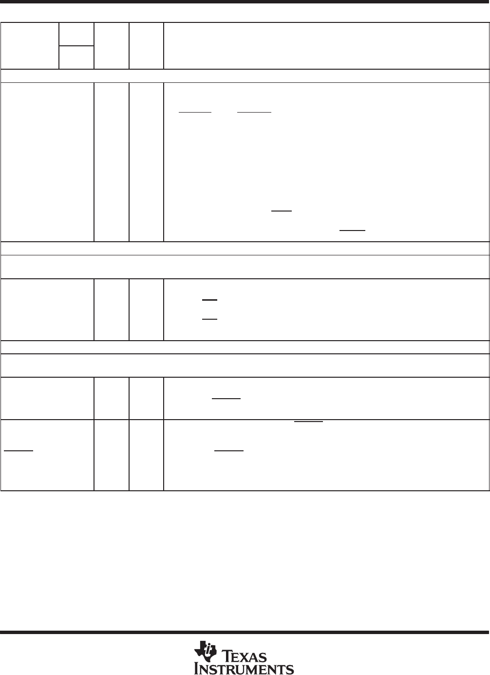
Terminal Functions (Continued)
SIGNAL
PIN
NO.
TYPE
†
IPD/
‡
DESCRIPTION
SIGNAL
NAME
GDP/
ZDP
TYPE
†
IPD/
IPU
‡
DESCRIPTION
JTAG EMULATION (CONTINUED)
EMU1
EMU0
B9
D9
I/O/Z IPU
Emulation [1:0] pins.
• Select the device functional mode of operation
EMU[1:0] Operation
00 Boundary Scan/Functional Mode (see Note)
01 Reserved
10 Reserved
11 Emulation/Functional Mode [default] (see the IEEE 1149.1
JTAG Compatibility Statement section of this data sheet)
The DSP can be placed in Functional mode when the EMU[1:0] pins are
configured for either Boundary Scan or Emulation.
Note: When the EMU[1:0] pins are configured for Boundary Scan mode, the
internal pulldown (IPD) on the TRST
signal must not be opposed in order to
operate in Functional mode.
For the Boundary Scan mode drive EMU[1:0] and RESET pins low.
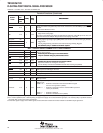
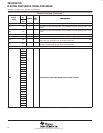
BOOTMODE
Note: If a configuration pin must be routed out from the device, the internal pullup/pulldown (IPU/IPD) resistor should not be relied upon; TI
recommends the use of an external pullup/pulldown resistor.
BOOTMODE1
BOOTMODE0
C19
C20
I IPD
Bootmode[1:0]
00 – Emulation boot
01 − CE1 width 8-bit, asynchronous external ROM boot with default timings
(default mode)
10 − CE1
width 16-bit, asynchronous external ROM boot with default timings
11 − Reserved, do not use
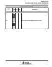
LITTLE/BIG ENDIAN FORMAT
Note: If a configuration pin must be routed out from the device, the internal pullup/pulldown (IPU/IPD) resistor should not be relied upon; TI
recommends the use of an external pullup/pulldown resistor.
LENDIAN B17 I IPU
Device Endian mode
0 – System operates in Big Endian mode.
The EMIFBE pin must be pulled low.
1 − System operates in Little Endian mode.
EMIFBE C15 I IPU
EMIF Big Endian mode correctness (EMIFBE)
When Big Endian mode is selected (LENDIAN = 0), for proper device
operation the EMIFBE
pin must be externally pulled low.
For more detailed information on the Big Endian mode correctness, see the EMIF Big Endian
Mode Correctness portion of this data sheet.
†
I = Input, O = Output, Z = High impedance, S = Supply voltage, GND = Ground, A = Analog signal (PLL Filter)
‡
IPD = Internal pulldown, IPU = Internal pullup. [To oppose the supply rail on these IPD/IPU signal pins, use external pullup or pulldown resistors
no greater than 4.4 kΩ and 2.0 kΩ, respectively.]