


TMS320C6712D
FLOATINGĆPOINT DIGITAL SIGNAL PROCESSOR
SPRS293A − OCTOBER 2005 − REVISED NOVEMBER 2005
24
POST OFFICE BOX 1443 • HOUSTON, TEXAS 77251−1443
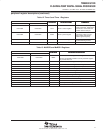
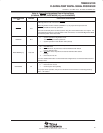
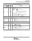
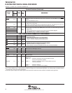
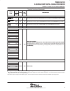
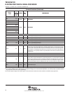
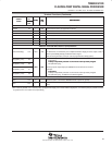
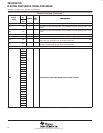
Terminal Functions
SIGNAL
PIN
NO.
TYPE
†
IPD/
‡
DESCRIPTION
SIGNAL
NAME
GDP/
ZDP
TYPE
†
IPD/
IPU
‡
DESCRIPTION
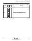
CLOCK/PLL
CLKIN A3 I IPU Clock Input
CLKOUT2 Y12 O/Z IPD
The CLKOUT2 pin is multiplexed with the GP[2] pin. Clock output at half of device speed (O/Z)
[default] (SYSCLK2 internal signal from the clock generator) or this pin can be programmed as
GP[2] (I/O/Z).
When the CLKOUT2 pin is enabled, the CLK2EN bit in the EMIF global control
register (GBLCTL) controls the CLKOUT2 pin (All devices).
CLK2EN = 0: CLKOUT2 is disabled
CLK2EN = 1: CLKOUT2 enabled to clock [default]
CLKOUT3 D10 O IPD Clock output programmable by OSCDIV1 register in the PLL controller
CLKMODE0 C4 I IPU
Clock generator input clock source select
0 − Reserved. Do not use.
1 − CLKIN square wave [default]
For proper device operation, this pin must be either left unconnected or
externally pulled up with a 1-kΩ resistor.
PLLHV C5 A Analog power (3.3 V) for PLL
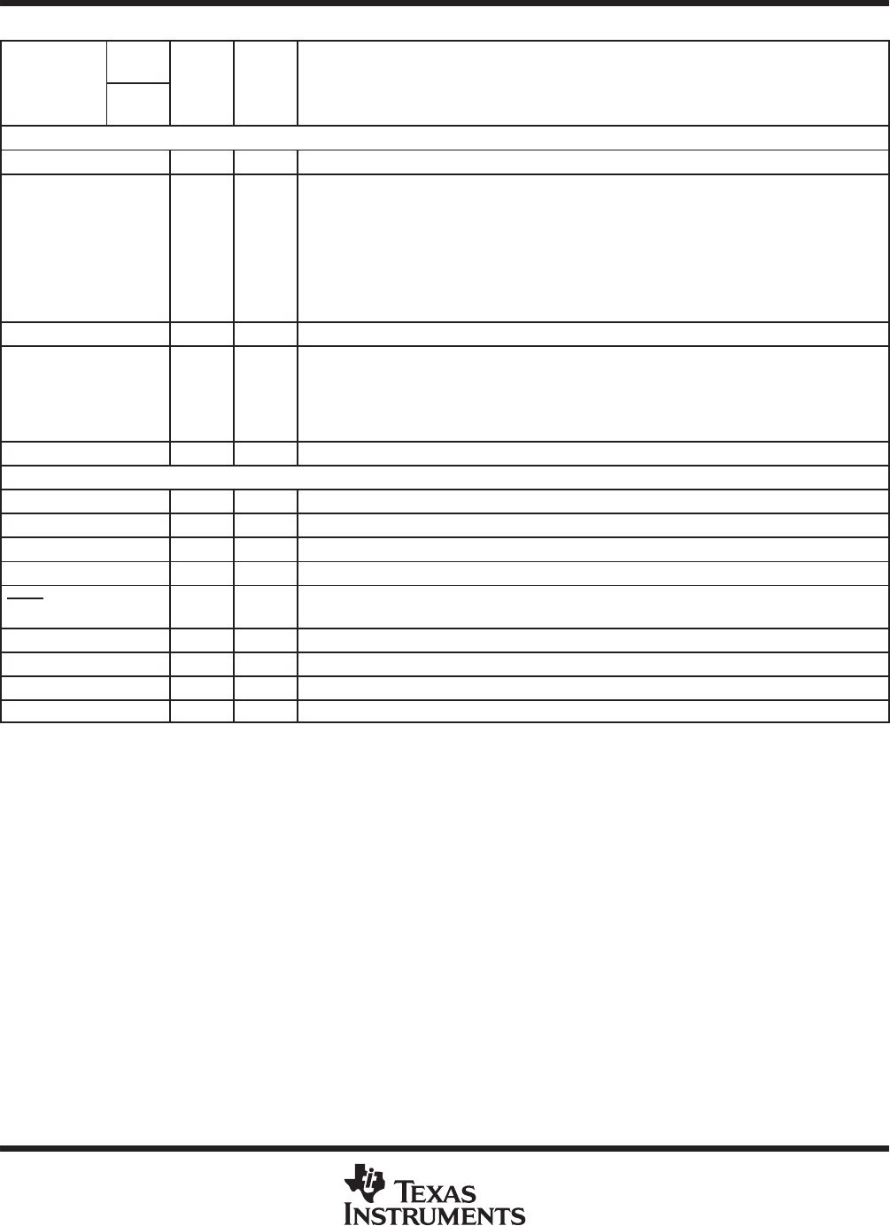
JTAG EMULATION
TMS B7 I IPU JTAG test-port mode select
TDO A8 O/Z IPU JTAG test-port data out
TDI A7 I IPU JTAG test-port data in
TCK A6 I IPU JTAG test-port clock
TRST
§
B6 I IPD
JTAG test-port reset. For IEEE 1149.1 JTAG compatibility, see the IEEE 1149.1
JTAG Compatibility Statement section of this data sheet.
EMU5 B12 I/O/Z IPU Emulation pin 5. Reserved for future use, leave unconnected.
EMU4 C11 I/O/Z IPU Emulation pin 4. Reserved for future use, leave unconnected.
EMU3 B10 I/O/Z IPU Emulation pin 3. Reserved for future use, leave unconnected.
EMU2 D3 I/O/Z IPU Emulation pin 2. Reserved for future use, leave unconnected.
†
I = Input, O = Output, Z = High impedance, S = Supply voltage, GND = Ground, A = Analog signal (PLL Filter)
‡
IPD = Internal pulldown, IPU = Internal pullup. [To oppose the supply rail on these IPD/IPU signal pins, use external pullup or pulldown resistors
no greater than 4.4 kΩ and 2.0 kΩ, respectively.]
§
To ensure a proper logic level during reset when these pins are both routed out and 3-stated or not driven, it is recommended that an external
10-kΩ pullup/pulldown resistor be included to sustain the IPU/IPD, respectively.