


TMS320C6712D
FLOATINGĆPOINT DIGITAL SIGNAL PROCESSOR
SPRS293A − OCTOBER 2005 − REVISED NOVEMBER 2005
28
POST OFFICE BOX 1443 • HOUSTON, TEXAS 77251−1443
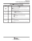
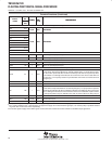
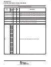
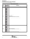
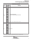
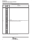
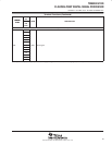
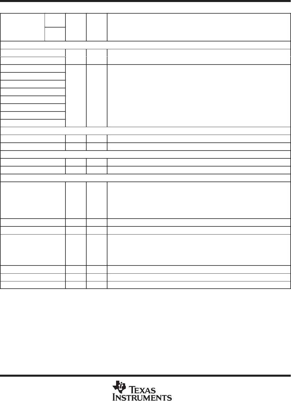
Terminal Functions (Continued)
SIGNAL
PIN
NO.
TYPE
†
IPD/
‡
DESCRIPTION
SIGNAL
NAME
GDP/
ZDP
TYPE
†
IPD/
IPU
‡
DESCRIPTION
EMIF − DATA (CONTINUED)
#
ED9 P18
I/O/Z
IPU
External data
ED8 N20
I/O/Z IPU External data
ED7 N19
ED6 N18
ED5 M20
ED4 M19
I/O/Z
IPU
External data
ED3 L19
I/O/Z IPU External data
ED2 L18
ED1 K19
ED0 K18
TIMER1
TOUT1 F1 O IPD Timer 1 or general-purpose output
TINP1 F2 I IPD Timer 1 or general-purpose input
TIMER0
TOUT0 G1 O IPD Timer 0 or general-purpose output
TINP0 G2 I IPD Timer 0 or general-purpose input
MULTICHANNEL BUFFERED SERIAL PORT 1 (McBSP1)
CLKS1 E1 I IPD
External clock source (as opposed to internal)
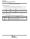
On this device, this pin does not have an internal pulldown (IPD). For proper device opera-
tion, the CLKS1 pin should either be driven externally at all times or be pulled up with a
10-kΩ resistor to a valid logic level. Because it is common for some ICs to 3-state their out-
puts at times, a 10-kΩ pullup resistor may be desirable even when an external device is
driving the pin.
CLKR1 M1 I/O/Z IPD Receive clock
CLKX1 L3 I/O/Z IPD Transmit clock
DR1 M2 I IPU
Receive data
On this device, this pin does not have an internal pullup (IPU). For proper device operation,
the DR1 pin should either be driven externally at all times or be pulled up with a 10-kΩ resis-
tor to a valid logic level. Because it is common for some ICs to 3-state their outputs at times,
a 10-kΩ pullup resistor may be desirable even when an external device is driving the pin.
DX1 L2 O/Z IPU Transmit data
FSR1 M3 I/O/Z IPD Receive frame sync
FSX1 L1 I/O/Z IPD Transmit frame sync
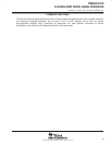
†
I = Input, O = Output, Z = High impedance, S = Supply voltage, GND = Ground, A = Analog signal (PLL Filter)
‡
IPD = Internal pulldown, IPU = Internal pullup. [To oppose the supply rail on these IPD/IPU signal pins, use external pullup or pulldown resistors
no greater than 4.4 kΩ and 2.0 kΩ, respectively.]
#
To maintain signal integrity for the EMIF signals, serial termination resistors should be inserted into all EMIF output signal lines.