


TMS320C6712D
FLOATINGĆPOINT DIGITAL SIGNAL PROCESSOR
SPRS293A − OCTOBER 2005 − REVISED NOVEMBER 2005
33
POST OFFICE BOX 1443 • HOUSTON, TEXAS 77251−1443
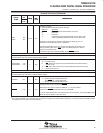
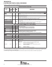
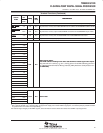
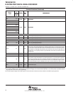
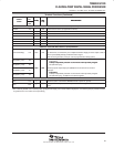
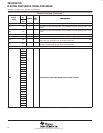
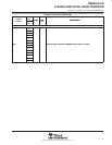
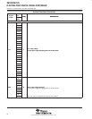
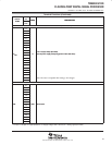
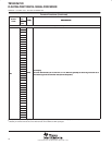
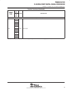
Terminal Functions (Continued)
SIGNAL
PIN
NO.
TYPE
†
DESCRIPTION
SIGNAL
NAME
GDP/
ZDP
TYPE
†
DESCRIPTION
SUPPLY VOLTAGE PINS (CONTINUED)
D11
D14
D15
F4
F17
K1
K4
K17
L4
L17
1.20-V supply voltage [See Note]
CV
DD
L20
S
1.20-V supply voltage [See Note]
(see the power-supply decoupling portion of this data sheet)
CV
DD
R4
S
(see the power-supply decoupling portion of this data sheet)
R17
U6
U10
U11
U14
U15
V3
V18
W2
Note: This value is compatible with existing 1.26-V designs.
W19
Note: This value is compatible with existing 1.26-V designs.
GROUND PINS
A1
A2
A11
A14
A19
A20
B1
V
SS
B4
GND
Ground pins
V
SS
B15
GND Ground pins
B20
C6
C8
C9
D4
D8
D13
†
I = Input, O = Output, Z = High impedance, S = Supply voltage, GND = Ground, A = Analog signal (PLL Filter)