4.8 Base assembly 4 Replacement Procedures
PORTÉGÉ R700 Maintenance Manual (960-833) [CONFIDENTIAL] 4-23
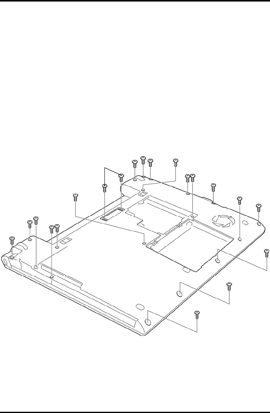
3. Remove the following screws securing the base assembly and cover assembly.
Dock model
• M2.5×6B FLAT HEAD screw ×15 (Described as “6” in the figure)
• M2.5×4B FLAT HEAD screw ×5 (Described as “4” in the figure)
Without Dock model
• M2.5×6B FLAT HEAD screw ×13 (Described as “6” in the figure)
• M2.5×4B FLAT HEAD screw ×5 (Described as “4” in the figure)
• M2.5×12B FLAT HEAD screw ×2 (Described as “12” in the figure)
Figure 4-12 Removing the base assembly (2)
6
4
6
6 (Dock model)
12 (Without Dock model)
6
6
6
6
6
6
6
6
6
6
6
4
4
4
4


