


System components
DocuTech 61xx Operator Guide 4-13
The paper paths
The path that the print stock takes as it moves through the
Processor and Finisher depends on the requirements of the job
and if there is an Interposer.
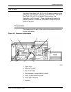
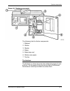
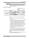
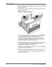
Figure 4-6. Paper path areas
The numbers in figure 4-6 identify the following paper path
areas:
• Areas 1 to 4 - The stock leaves a paper tray and is fed to the
photoreceptor.
• Areas 5 to 10 - The system prints an image on one side of the
stock. If the job requires 2-sided printing, the system turns
the page over and feeds it back to the photoreceptor.
• Areas A to H - This is the interposer area. Paper travels
through this area if paper is fed from trays 1, 4 or 5 and also
to pass paper from area 10 (through F and H) to the finisher.
• Areas 11 and 12 - If the prints are to be fed to the top tray, the
system delivers the prints through the top tray slot.
• Areas 13 to 16 - The prints enter the bindexer and are
collated, if desired.
• Areas 17 to 19 - The prints are stitched in area 17, or bound
in area 18, if desired, and placed on the stacker in area 19.
If a paper jam occurs, the system displays a message on the
controller that shows the number of the area where the jam
occurred.
NOTE: For information about clearing a paper jam, refer to the
"Problem solving" chapter of this guide.