


Chapter 3 Hardware Overview
XGS-4526/4528F/4728F User’s Guide
41
3.2 Rear Panel
3.2.1 XGS-4526
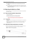
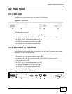
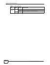
The following figure shows the rear panel of the Switch.
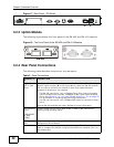
Figure 15 Rear Panel
The rear panel contains:
• A connector for the backup power supply (A)
• An optional slot (B) for installing an EM-422 or EM-412 uplink module
• An RJ-45 out-of-band management port (C)
• An RS-232 management console port (D)
• A connector for the power receptacle (E)
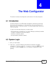
3.2.2 XGS-4528F or XGS-4728F
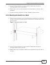
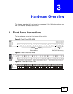
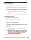
The following figures show the rear panels of the AC and DC power input model
switches. The rear panels contain:
• A connector for the backup power supply (A)
• An optional slot (B) for installing an EM-422 or EM-412 uplink module
• Two stacking ports (C)
• An RJ-45 out-of-band management port (D)
• An RS-232 management console port (E)
• A connector for the power receptacle (F)
•A power switch (G) (DC power input model only).
Figure 16 Rear Panel - AC Model
B
D
E
A
C
BDEFA
C