


Chapter 3 Hardware Overview
XGS-4526/4528F/4728F User’s Guide
42
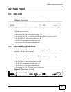
Figure 17 Rear Panel - DC Model
3.2.3 Uplink Module
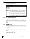
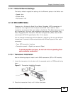
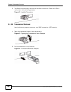
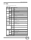
The following figure shows the front panel of the EM-422 and EM-412 modules.
Figure 18 The Front Panel of the EM-422 and EM-412 Modules
3.2.4 Rear Panel Connections
The following table describes the ports on the rear panel.
G
F
EM-412
EM-422
Table 2 Panel Connections
CONNECTO
R
DESCRIPTION
Optional two
XFP or CX4
Ports
These ports are available when you install an EM-422 or ES-412 in the
optional uplink module (B in the figure above). Both the EM-422 and ES-
412 are used to connect your switch to other high-speed Ethernet
switches for stacking in you network.
• For EM-422 connection: Use 10 Gigabit Small Form Factor Pluggable
(XFP) transceivers to connect 1000Base-X fiber-optic cables to these
ports. See Section 3.1.3.1 on page 39 and Section 3.1.3.2 on page 40
for information on installing and removing transceivers.
• For EM-412 connection: Use 10GBase-CX4 cables to connect to these
ports.
See the EM-422 and EM-412 User’s Guides for more information.
Two stacking
ports
(XGS-4528F
or XGS-
4728F)
Connect these ports to other XGS-4528F or XGS-4728F switches for
stacking using stacking cables.
Management
Port
Connect to a computer using an RJ-45 Ethernet cable for local
configuration of the Switch.
Console Port Only connect this port to your computer (using an RS-232 cable) if you
want to configure the Switch using the command line interface (CLI) via
the console port.