


Installing the Network Driver 3-13
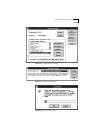
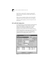
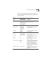
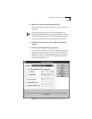
Table 3-1 describes the fields and buttons in the ATMLink
Installation and ELAN Configuration windows. Default values
are shown in bold.
Table 3-1 3C975 ATMLink NIC Installation Configuration Parameters
Field
Range of Values
(Defaults in Bold)
Description
ATMLink NIC All ATMLink NICs with
installed drivers by PCI
slot, bus number, and
MAC address (after
initial installation)
Select the NIC you wish to configure
from the drop-down list.
Global NIC Parameters (must be the same for all NICs in a computer system)
VPI/VCI Range 0 bits/12 bits
1 bits/11 bits
2 bits/10 bits
8 bits/4 bits
This parameter is determined by the
ATM switch setting.
Signaling UNI v3.0
UNI v3.1
This parameter is determined by the
ATM switch setting.
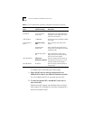
Local NIC Parameters (specific to each NIC in a computer system)
LAN Type Ethernet (802.3)
Token Ring (802.5)
All ELANs configured on a NIC must be
the same LAN type.
ILMI VPI 0 This parameter is determined by the
ATM switch setting.
ILMI VCI 16 This parameter is determined by the
ATM switch setting.
Maximum Frame Size 1514
4542
9232
All ELANs on the same NIC have the
same MFS value, also called maximum
transfer unit (MTU). Use 1514 for
Ethernet, 4542 for 4 Mbps token ring,
and 9232 for 16 Mbps token ring.
Only end stations using the same value
can interoperate.
Resilient Server Link Any active NIC Select one or more eligible active NICs
to make the current ATMLink NIC a
standby NIC.
(continued)