


Configuring LECs and Resilient Server Links 4-11
Configuring LECs and Resilient Server Links
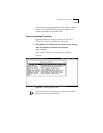
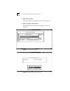
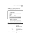
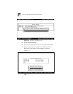
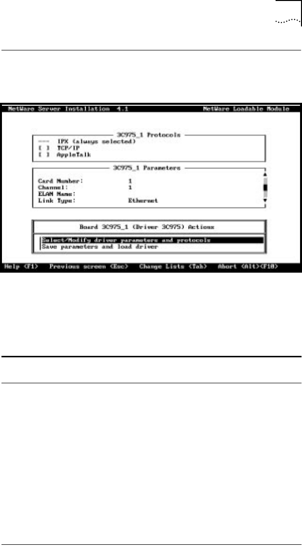
After the driver files are copied to the server, the
ELAN Configuration screen appears, as shown in Figure 4-7.
Figure 4-7 ELAN Configuration Screen
Table 4-1 lists the configuration parameters of the 3Com
ATMLink NIC, the range of values, and parameter descriptions.
Default values are shown in bold.
Table 4-1 3C975 ATMLink NIC NetWare Install Utility Configuration Parameters
Parameter
Range of Values
(Defaults in Bold)
Description
Card Number 1, 2, 3, 4 This number denotes which physical NIC
is being configured.
Channel 1–64 Use a unique channel number for each
ELAN and standby NIC in the system
(16 ELANs per NIC, 4 NICs per system).
ELAN Name 1- to 32-character ASCII
string
ELAN names should match ELAN names
configured on the ATM switch.
Link Type Ethernet
Token ring
All ELANs with the same card number
must have the same link type. A standby
NIC must have the same link type as its
active NICs.
Home Card <blank>, 1, 2, 3, 4 If Card Number=3 and Home=2,1 then
Card 3 is a standby NIC for Card 2 and
Card 1.
(continued)