


3Com Router 5000 and Router 6000 v2.41
Module Guide
Chapter 3
Multifunctional Interface Modules (Router 5000)
3-59
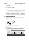
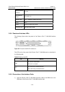
Cable characteristic
impedance
100 ohm
Max transmission
distance
150 m (492.1 in.)
Operating mode ATM T1 standalone link/IMA binding mode
Service AAL5
Protocol PPPoA, PPPoEoA, IPoA, IPoEoA
Transmission rate CBR/VBR-rt/VBR-nrt/UBR
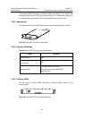
3.15.4 Panels and Interface LEDs
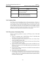
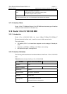
The following figures show the panels of the Router 4-Port T1 IMA MIM interface
cards:
Figure 3-63 Front panel of the IMA-4T1 interface card
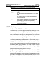
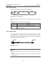
The LEDs on the front panel of the Router 4-Port T1 IMA MIM panel, as described in
the following table:
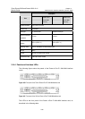
Table 3-37 Meaning of the LEDs
LED Meaning
LINK
OFF: the link is disconnected.
ON: the link is connected.
ACT
Blink: data is being transmitted/received.
Off: no data is being transmitted/received.
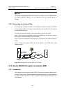
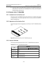
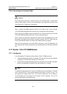
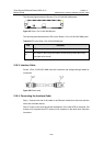
3.15.5 Connection of the Interface Cable
1) Insert the Router 4-Port T1 IMA MIM conversion cable at the DB68 end to the
DB68 port of the Router 4-Port T1 IMA MIM interface card.