


3Com Router 5000 and Router 6000 v2.41
Module Guide
Chapter 2 Smart Interface Cards
2-31
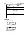
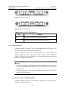
Description of the LEDs on Router 1-Port SAE SIC panel is given in the following table:
Table 2-19 LEDs on Router 1-Port SAE SIC panel
LED Description
LINK OFF means no link is present; ON means a link is present.
ACT
OFF means no data is being transmitted or received; blinking
means data is being received or/and transmitted.
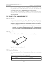
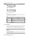
2.8.4 Interface Cable
The Router 1-Port SAE SIC uses a synchronous/asynchronous serial interface cable
with DB-28 connectors for connection.
Before connecting to a port on the Router 1-Port SAE SIC, confirm the line properties
of the interface to select an appropriate cable from the following cable options:
z V.24 (RS232) DTE cable: DB-25 (male) connector at the network end
z V.24 (RS232) DCE cable: DB-25 (female) connector at the network end
z V.35 DTE cable: 34PIN (male) connector at the network end
z V.35 DCE cable: 34PIN (female) connector at the network end
z X.21 DTE cable: DB-15 (male) connector at the network end
z X.21 DCE cable: DB-15 (female) connector at the network end
z RS449 DTE cable: DB-37 (male) connector at the network end
z RS449 DCE cable: DB-37 (female) connector at the network end
z RS530 DTE cable: DB-25 (male) connector at the network end
z RS530 DCE cable: DB-25 (female) connector at the network end
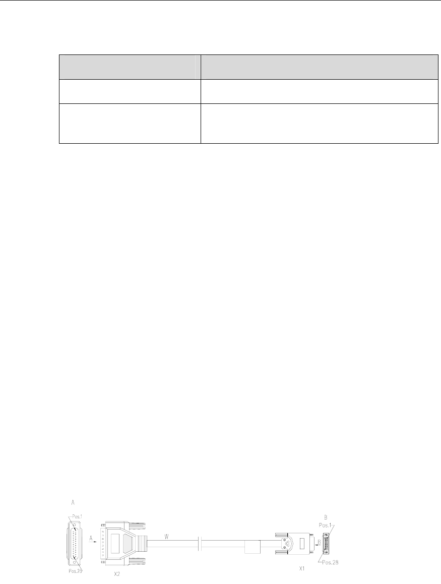
At one end of these cables is a DB-28 connector and at the other end is the connector
that varies with the port at the network side.
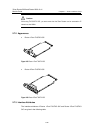
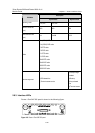
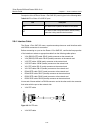
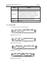
z V.24 DTE cable
Figure 2-32 V24 DTE cable
z V.24 DCE cable