


3Com Router 5000 and Router 6000 v2.41
Module Guide
Chapter 4 Flexible Interface Cards (Router 6000)
4-8
4.3.3 Panel and Interface LEDs
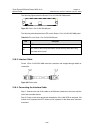
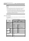
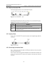
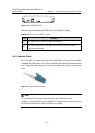
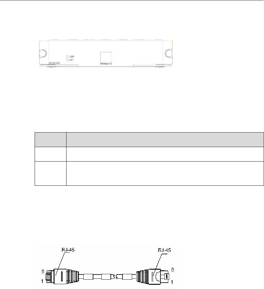
The following figures show the 1-Port 10/100/1000 FIC panel.
Figure 4-6 1-Port 10/100/1000 FIC, panel
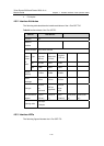
The following table describes the LEDs on the Router 1-Port 10/100/1000 FIC panel.
Table 4-6 LEDs on the Router 1-Port 10/100/1000 FIC panel
LED Description
LINK OFF means no link is present; ON means a link is present.
ACT
OFF means no data is being transmitted or received. Blinking means data is being
transmitted and/or received.
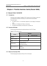
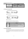
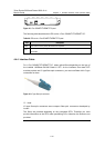
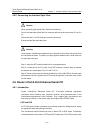
4.3.4 Interface Cable
Router 1-Port 10/100/1000 FIC uses both crossover and straight-through cables for
connection.
Figure 4-7 Ethernet cable
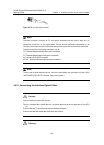
4.3.5 Connecting the Interface Cable
Step 1: Connect one end of the cable to the Ethernet interface on the router and the
other end to another device.
Step 2: Power on the router and check the behavior of the LINK LED on the panel. ON
means a link is present and OFF means no link is present. In the latter case, check the
line status.