


3Com Router 5000 and Router 6000 v2.41
Module Guide
Chapter 4 Flexible Interface Cards (Router 6000)
4-27
z If the to-be-connected network device has a 120-ohm port, you need a
75-ohm-to-120-ohm adapter or a 120-ohm cable instead.
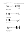
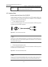
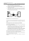
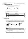
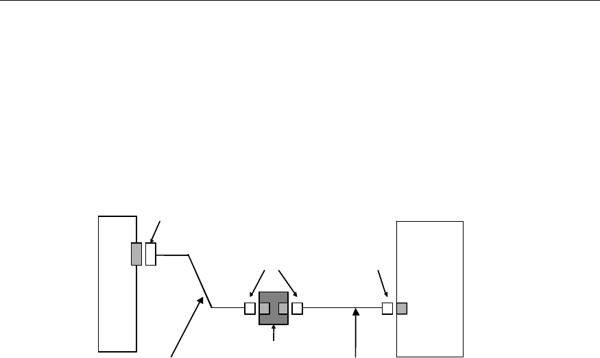
2) When using a 120-ohm balanced twisted-pair cable, do the following:
z If no cable extension is needed, directly connect the RJ-45 connector of the cable
to the RJ-45 port on the device.
z If cable extension is needed, connect the RJ-45 connector of the cable to a
network interface connector, and the other end of the network interface connector
to the device using a 120-ohm E1 trunk cable.
Router
Network
devices such
as DDN
DB-15
Network interface connector
RJ-45 RJ-45
120-ohm balanced twisted pair
120-ohm E1 trunk cable
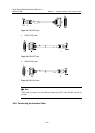
Router
Network
devices such
as DDN
DB-15
Network interface connector
RJ-45 RJ-45
120-ohm balanced twisted pair
120-ohm E1 trunk cable
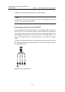
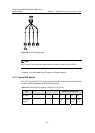
Figure 4-30 Extending an E1 120-ohm balanced twisted-pair cable
Step 4: Power on the router, and check the behavior of the LINK LED on the card: OFF
means fault occurs on the line and the signal is not synchronized. Check the line
status.
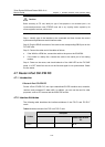
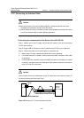
II. Connecting the interface cable of the Router 4-Port CE1/PRI FIC
Step 1: Select the cable appropriate to the type of the port on the to-be-connected
device, and correctly set the DIP switch.
z If the impedance of the to-be-connected port is 75-ohm, select E1 75-ohm
unbalanced coaxial and 75-ohm 4E1 adapter cables, and set all the BITs of the
DIP switch to the ON position (that is, the port impedance is 75-ohm).
z If the impedance of the to-be-connected port is 120-ohm, select E1 120-ohm
balanced twisted-pair and 120-ohm 4E1 adapter cables, and set all the BITs of
the DIP switch to the OFF position (that is, the port impedance is 120-ohm).
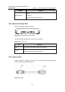
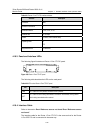
Step 2: Insert the DB-25 connector of the 4E1 adapter cable into the to-be-connected
port on the Router 4-Port CE1/PRI FIC and tighten the thumbscrews.
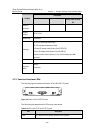
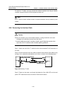
Step 3: Identify the sequence number of the DB-15 connector at the other end of the
cable, and connect the connector to an E1 cable.
Step 4: Connect the E1 cable to another device, by reference to the previous
subsection.