


3Com Router 5000 and Router 6000 v2.41
Module Guide
Chapter 3
Multifunctional Interface Modules (Router 5000)
3-40
z If the port on the network device to be connected has a 120-ohm port, use a
75-ohm to 120-ohm adapter, or use a 120-ohm cable instead.
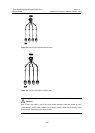
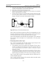
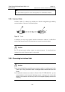
2) When using a 120-ohm balanced twisted pair cable,
z Connect its RJ-45 connector to the RJ-45 port on the device to be connected
directly, if cable extension is not needed.
z Connect its RJ-45 connector to a network interface connector and then the other
end of the network interface connector to the network device to be connected
through a 120-ohm E1 trunk cable, if cable extension is needed.
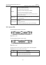
Router
Network
devices such
as DDN
DB-15
Network interface connector
RJ-45
RJ-45
120-ohm balanced twisted pair
120-ohm E1 trunk cable
Figure 3-46 Extending an 120-ohm balanced twisted pair cable
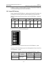
Step 4: Power on the Router, and check the LEDs of the corresponding slot on the
front panel: ON means that the MIM is operating normally and OFF means that the
POST of the MIM has failed. In the latter case, please contact your agent;
Step 5: Check the behavior of the LINK LED on the module panel. It is OFF when fault
has occurred on the link and signal is out of synchronization. In this case, please
check the link.
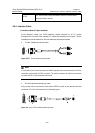
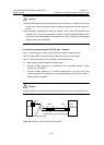
II. Connecting interface cable of 4-port
Step 1: Select the appropriate cable and cable according to type of the port on the
remote device, and set DIP switches of module correctly;
z If the resistance of the port on the device to be connected is 75-ohm, select a
75-ohm E1 non-balanced coaxial cable and a 75-ohm 4E1 conversion cable, and
set all the DIP switches on the 4E1/4E1-F module to “ON” (that is, the port
resistance is 75-ohm).
z If the resistance of the port on the device to be connected is 120-ohm, select a
120-ohm balanced twisted pair cable and a 120-ohm conversion cable, and set all
the DIP switches on the module to “OFF” (that is, the port resistance is 120-ohm).
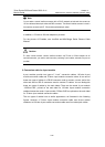
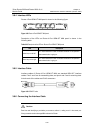
Step 2: Plug the DB-25 connector of the conversion cable into a DB-25 port on or
module, and tighten the screws;
Step 3: Connect the DB-15 connector of the conversion cable to the cable, making
sure of wire sequence of the connector;