


3Com Router 5000 and Router 6000 v2.41
Module Guide
Chapter 3
Multifunctional Interface Modules (Router 5000)
3-5
II. Interface cable of E&M modules
E&M modules of 3Com 5000 Family Routers support Bell I, II, III, V switches, and
2-wire & 4-wire voice signals.
It is recommended to use Bell V 4-wire voice signal to communicate with the Router in
practice.
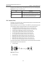
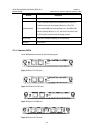
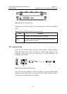
The sequence of E&M RJ45 pins is shown in the following figure, numbered 1 to 8
from left to right:
Figure 3-9 Sequence of RJ45 pins
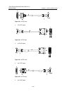
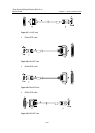
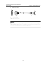
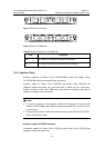
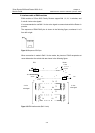
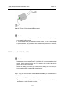
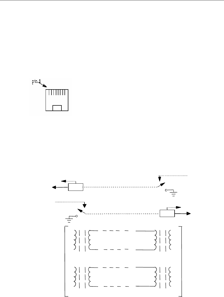
When connection is made in Bell V 4-wire mode, the pinouts of RJ45 receptacles at
router side and at the switch side are shown in the following figure:
-48V
PBX
Router
detect
M
E
7
on-hook
off-hook
on-hook
-48V
on-hook
detect
M
E
2
off-hook
4- wire
6
T0
R0
T1
T1
R1
R1
R0
T0
4
5
3
4- wire
voice signal
-48V
voice signal
Figure 3-10 E&M interface cable (Bell V 4-wire)