


3Com Router 5000 and Router 6000 v2.41
Module Guide
Chapter 2 Smart Interface Cards
2-18
Note:
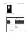
A network interface connector is available for extending the E1 cable. Both ends of the connector are
RJ45 jacks that can be used to connect two 120-ohm balanced twisted pair cables.
In addition, a 75-ohm to 120-ohm adapter is available.
For the pinouts of E1 cables, see Low-End and Mid-Range Series Routers Cable
Manual.
Caution:
E1 cable, coaxial connector, network interface connector and 75ohm-to-120ohm adapter are optional,
which must be ordered together with Router 1-Port Fractional E1 SIC. Otherwise they will not be
supplied.
2.4.7 Connecting Interface Cable
Caution:
When using E1 cable outdoors, you are recommended to install a special lightning arrester on the input
end of the cable in order to avoid lightning more effectively.
If the SIC has been properly installed, follow these steps to connect the cable:
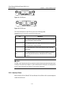
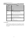
Step 1: Check the type of E1 cable and correctly set the DIP switch (the ex-factory
setting of E1/cE1/PRI interface impedance is 75-ohm);
Step 2: Connect the DB15 connector of E1 cable to Router 1-Port Fractional E1 SIC;
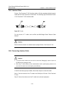
Step 3: Connect the other end of the E1 cable to the corresponding network device:
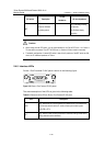
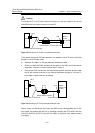
1) When the E1 cable is a 75-ohm unbalanced coaxial cable:
z Directly connect the BNC connector of the cable to the remote equipment if there
is no need for extension, or
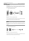
z Connect the BNC connector of the cable to the coaxial connector and the other
end of the coaxial connector to the remote network equipment through a 75-ohm
E1 trunk cable, if cable extension is needed.