


3Com Router 5000 and Router 6000 v2.41
Module Guide
Chapter 2 Smart Interface Cards
2-19
Caution:
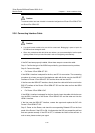
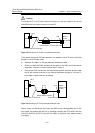
The wire marked TX in the E1 cable should be connected to the peer wire marked RX and the wire
marked RX should be connected to the peer wire marked TX.
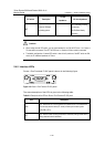
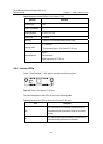
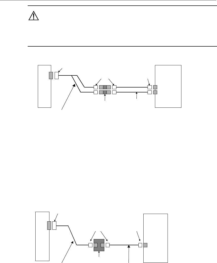
Router
Network
devices
such as DDN
DB-15
Coaxial connector
BNC
BNC
75-ohm non-balanced coaxial cable
75-ohm E1 trunk cable
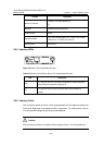
Figure 2-18 Extending an E1 75-ohm non-balanced coaxial cable
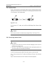
If the remote device has 120-ohm interface, it is needed to use a 75-ohm-to-120-ohm
adapter or use a 120-ohm cable.
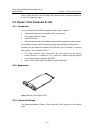
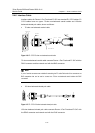
2) When the E1 cable is a 120-ohm balanced twisted pair cable:
z Directly connect the RJ45 connector of the cable to the RJ45 port of the remote
equipment, if there is no need to extend the E1 cable, or
z Connect the RJ45 connector of the cable to the network connector and the other
end of the network connector to the network equipment through a 120-ohm E1
trunk cable, if cable extension is needed.
Router
Network
devices such
as DDN
DB-15
Network interface connector
RJ-45
RJ-45
120-ohm balanced twisted pair
120-ohm E1 trunk cable
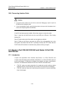
Figure 2-19 Extending an E1 120-ohm balanced twisted pair cable
Step 4: Power on the Router, and check the LEDs of the corresponding slot on the
front panel: ON means that the SIC is operating normally and OFF means that the
Power-On Self-Test (POST) of the SIC has failed. In the latter case, please contact
your agent;