


3Com Router 5000 and Router 6000 v2.41
Module Guide
Chapter 3
Multifunctional Interface Modules (Router 5000)
3-43
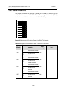
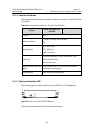
3.9.4 Interface LEDs
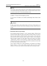
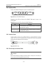
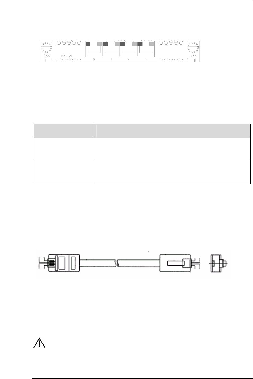
Router 4-Port ISDN-S/T MIM panel is shown in the following figure:
Figure 3-48 Router 4-Port ISDN-S/T MIM panel
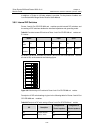
Description of the LEDs on Router 4-Port ISDN-S/T MIM panel is shown in the
following table:
Table 3-25 Description of the LEDs on Router 4-Port ISDN-S/T MIM panel
LED Description
Yellow lamp on the left
OFF means channel B1 is idle. ON means channel B1 is occupied and
data communication is going on.
Green lamp on the right
OFF means channel B2 is idle. ON means channel B2 is occupied and
data communication is going on.
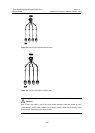
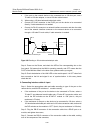
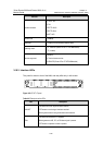
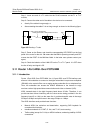
3.9.5 Interface Cable
Interface cables of Router 4-Port ISDN-S/T MIM are standard ISDN S/T interface
cables. Pins 3 and 6 are for transmitting data, and pins 4 and 5 are for receiving data.
At both ends of the cables are RJ-45 connectors.
Green
Yellow
Red
Black
Yellow
Green
Black
Red
Green
Yellow
Red
Black
Yellow
Green
Black
Red
Figure 3-49 ISDN S/T cable
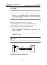
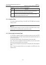
3.9.6 Connecting the Interface Cable
Caution:
Read the mark identifying a port before you connect a cable to it, making sure it is the correct port.
Wrong connection tends to damage MIMs and even the Router.