


3Com Router 5000 and Router 6000 v2.41
Module Guide
Chapter 3
Multifunctional Interface Modules (Router 5000)
3-14
Caution:
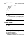
Both Router T1 Voice Module cable and network interface connector are optional accessories. You
should order them when ordering a Router T1 Voice Module. Otherwise, they will not be provided.
3.3.6 Connecting Interface Cable
Caution:
z Some measures are taken to protect Router T1 Voice Module. Still, you are recommended to install
a special lightning arrester at the input end of its connection cable to obtain better lightning
protection when the cable is led outdoors;
z Read the mark identifying a port before you connect a cable to it, making sure it is the correct port.
Wrong connection tends to damage interface modules and even the Router.
Step 1: Insert one end of a Router T1 Voice Module cable into the DB15 port on the
Router T1 Voice Module;
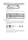
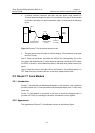
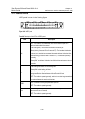
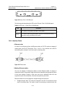
Step 2: Connect the other end of the Router T1 Voice Module cable to:
z The peer device if the cable is long enough;
z A network interface connector and then the peer device using another Router T1
Voice Module cable, if it is not long enough, as shown in the following figure:
Router
Voice
device
DB15
Network interface connector
RJ45
Straight-through network cable
RJ45
T1VI cable
Figure 3-19 Extending a Router T1 Voice Module cable
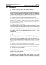
Step 3: Power on the Router, and check the LEDs of the corresponding slot on the
front panel of the Router: ON means Router T1 Voice Module is operating normally
and OFF means the POST of Router T1 Voice Module has failed. In the latter case,
please contact your agent;
Step 4: Check the status of the LINK LED on the Router T1 Voice Module panel. It is
OFF when fault has occurred to the link. In this case, please check the link.