


3Com Router 5000 and Router 6000 v2.41
Module Guide
Chapter 2 Smart Interface Cards
2-12
Caution:
The relevant cables have been included in the standard configurations of Router 2-Port ISDN-S/T SIC
and Router 2-Port ISDN-U SIC.
2.3.6 Connecting Interface Cable
Caution:
z You should connect a cable to the port with the correct mark. Misplugging is prone to impair the
SIC/MIM and even damage the router.
z When using a telephone cable with ferrite core outdoors, you are recommended to install a special
lightning arrester on the input end of the cable in order to avoid lightning more effectively.
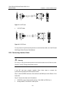
If the SIC has been properly installed, follow these steps to connect the cable:
Step 1: Confirm the type of the ISDN line provided by your telecom service provider;
Step 2: Connect the cable;
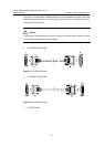
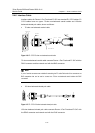
z For Router 2-Port ISDN-S/T SIC
If the ISDN U interface is adopted for the line, use NT1 for conversion. The connecting
procedure is to insert one end of the telephone cable with ferrite core into the BRI S/T
interface of Router 2-Port ISDN-S/T SIC and the other end into the NT1.
If the line uses the ISDN S/T interface, directly insert the cable with ferrite core into the
BRI S/T interface of the Router 2-Port ISDN-S/T SIC and the other end into the ISDN
S/T interface.
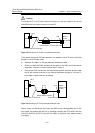
z For Router 2-Port ISDN-U SIC
If the ISDN U interface is adopted for the line, directly insert the cable with ferrite core
into the BRI U interface of the Router 2-Port ISDN-U SIC and the other end into the
ISDN U interface.
If the line uses the ISDN S/T interface, contact the agent and replace the SIC with
Router 2-Port ISDN-S/T SIC.
Step 3: Power on the Router, and check the corresponding Related LED on the front
panel of the Router. If the LED is ON, it indicates that the SIC has passed the self-test
and can operate normally. If the LED is OFF, it indicates the failure of the self-test. In
such a case, please contact your agent.