


3Com Router 5000 and Router 6000 v2.41
Module Guide
Chapter 4 Flexible Interface Cards (Router 6000)
4-26
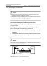
4.7.6 Connecting the Interface Cable
Caution:
Before you connect a port, read its label carefully; a wrong connection can cause
damages to the interface card and even the device.
If outdoor cabling is involved, consider to install a special lightning arrester at the input
end of the interface cable for better lightning protection.
I. Connecting the interface cable of the Router 4-Port CE1/PRI FIC
Step 1: Identify type of the E1 cable, and set the DIP switch for the to-be-connected
E1/FE1 port correctly.
Step 2: Plug the DB-15 connector of the E1 cable into the E1/FE1 port on the card.
Step 3: Connect the other end of the E1 cable to another device.
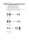
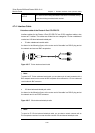
1) When using a 75-ohm unbalanced coaxial cable, do the following:
z If no cable extension is needed, directly connect the BNC connector of the cable
to the device.
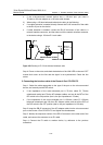
z If cable extension is needed, connect the BNC connector of the cable to a coaxial
connector, and then connect the other end of the coaxial connector to the device
using a 75-ohm E1 trunk cable.
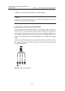
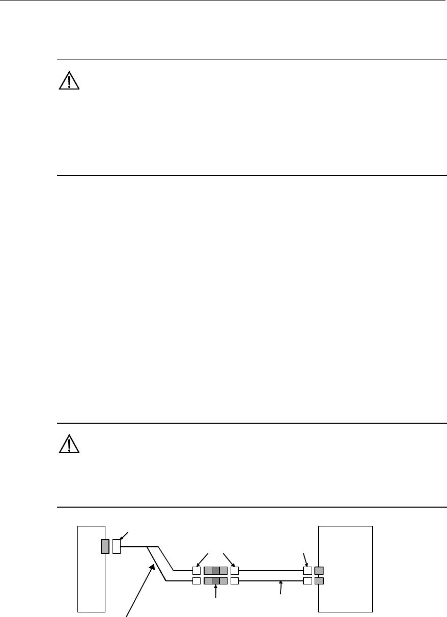
Caution:
When connecting the router to another device using an E1 coaxial cable, make connection with the TX
end to the RX end and the RX end to the TX end.
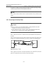
Router
Network
devices
such as DDN
DB-15
Coaxial connector
BNC
BNC
75-ohm non-balanced coaxial cable
75-ohm E1 trunk cable
Router
Network
devices
such as DDN
DB-15
Coaxial connector
BNC
BNC
75-ohm non-balanced coaxial cable
75-ohm E1 trunk cable
Figure 4-29 Extending an E1 75-ohm unbalanced coaxial cable