


3Com Router 5000 and Router 6000 v2.41
Module Guide
Chapter 4 Flexible Interface Cards (Router 6000)
4-54
4.17.3 Panel and Interface LEDs
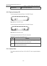
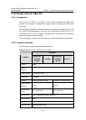
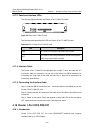
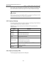
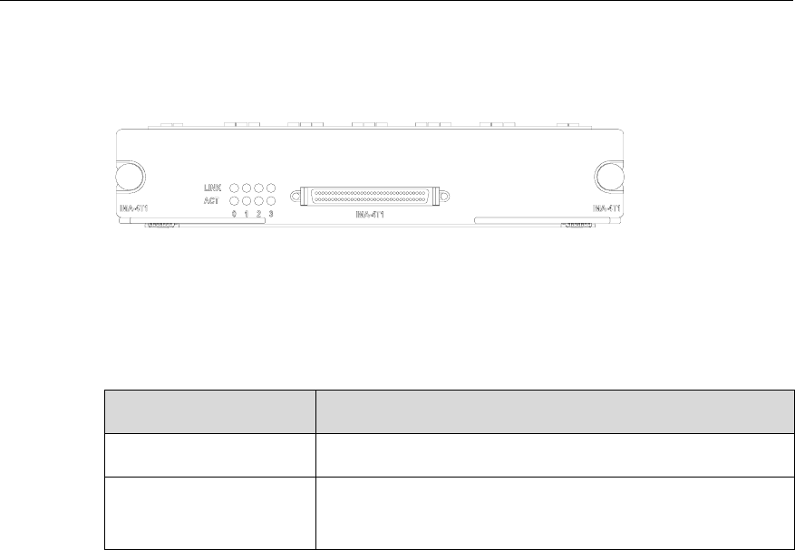
The following figures illustrate the Router 4-Port T1 IMA FIC panels:
Figure 4-53 Router 4-Port T1 IMA FIC panel
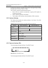
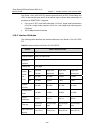
The following table describes the LEDs on Router 4-Port T1 IMA FIC panel:
Table 4-36 LEDs on Router 4-Port T1 IMA FIC/ panel
LED Description
LINK OFF means no link is present; ON means a link is present.
ACT
OFF means no data is being transmitted or received; blinking means
data is being received and/or transmitted.
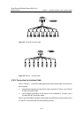
4.17.4 Interface Cable
The Router 4-Port T1 IMA FIC card provides four or eight T1 ports and uses the 4T1
conversion cable for connection. At one end of the cable is a DB-68 connector for
connecting the router and at the other end are four or eight RJ-45 connectors for
connecting other devices.
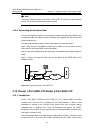
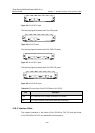
4.17.5 Connecting the Interface Cable
Step 1: Insert the DB-68 connector of the conversion cable to the DB-68 port on the
Router 4-Port T1 IMA FIC card.
Step 2: Connect one RJ-45 connector at the other end of the cable to the device to be
connected.
Step 3: Power on the router. Check the behavior of the LINK LED on the card panel:
OFF means fault has occurred on the link. Check the line status.
4.18 Router 1-Port OC3 POS FIC
4.18.1 Introduction
Router 1-Port OC3 POS FIC, the 1-port SDH/SONET interface card, supports
interface rates up to 155.52 Mbps.