


3Com Router 5000 and Router 6000 v2.41
Module Guide
Chapter 3
Multifunctional Interface Modules (Router 5000)
3-11
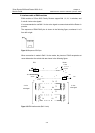
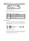
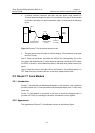
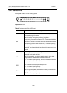
z A network interface connector and then the peer device using another E1
120-ohm balanced twisted pair cable, if the resistance of the port to be connected
is 120-ohm, and there is a need to extend the cable, as illustrated in the following
figure.
Router
Voice
Device
DB-15
Network interface
RJ-45
RJ-45
120-ohm balanced
120-ohm E1
trunk cable
twisted pair cable
connector
Figure 3-15 Extending E1 120-ohm balanced twisted pair cable
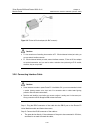
z The peer device using a 75ohm-to-120ohm adapter, if the resistance of the peer
device is 75-ohm;
Step 3: Power on the Router, and check the LEDs of the corresponding slot on the
front panel: ON means Router E1 Voice Module is operating normally and OFF means
the POST of Router E1 Voice Module has failed. In the latter case, please contact your
agent;
Step 4: Check the status of the LINK LED on the Router E1 Voice Module panel. It is
OFF when fault has occurred to the link. In this case, please check the link.
3.3 Router T1 Voice Module
3.3.1 Introduction
Router T1 Voice Module can handle dense signals in VoIP systems. It can implement
the VoIP function over T1 lines and transmit voice and data signals over T1 lines at the
same time.
Router T1 Voice Module is structured in the form of board plus daughter card. It
provides a CT1/PRI port, allowing the access of 24 channels of voice signals.
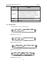
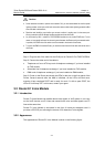
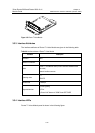
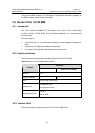
3.3.2 Appearance
The appearance of Router T1 Voice Module is shown in the following figure: