


3Com Router 5000 and Router 6000 v2.41
Module Guide
Chapter 4 Flexible Interface Cards (Router 6000)
4-32
4.9.3 Panel and Interface LEDs
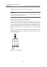
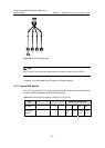
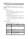
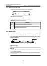
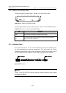
The following figure illustrates an Router 1-Port CE3 FIC panel.
Figure 4-34 Router 1-Port CE3 FIC panel
The following table describes the LEDs on the card panel.
Table 4-20 LEDs on the Router 1-Port CE3 FIC panel
LED Description
LINK OFF means no link is present; ON means a link is present.
ACT
OFF means no data is being transmitted or received on the interface; blinking means
data is being transmitted and/or received.
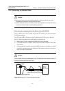
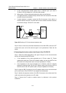
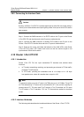
4.9.4 Interface Cable
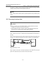
The external interface provided by the Router 1-Port CE3 FIC uses two SMB sockets
respectively for data transmitting (Tx) and data receiving (Rx). The interface transmits
in 75-ohm unbalanced mode and uses a pair of 75-ohm unbalanced coaxial cables to
connect another device.
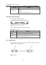
BNC connector SMB connectorBNC connector SMB connectorBNC connector SMB connectorBNC connector SMB connectorBNC connector SMB connector
Figure 4-35 E3/T3 cable
Note:
The Router 1-Port CE3 FIC and the Router 1-Port CT3 FIC use the same cable, called
E3/T3 cable in this manual.
The standard equipping package of the Router 1-Port CE3 FIC includes the required
interface cable.