


3Com Router 5000 and Router 6000 v2.41
Module Guide
Chapter 3
Multifunctional Interface Modules (Router 5000)
3-37
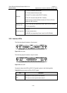
In addition, a 75-ohm to 120-ohm adapter is provided. For the pinouts of cables, see
Low-End and Mid-Range Series Routers Cable Manual.
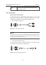
3.8.5 Internal DIP Switches
Router 2 and 4-Port CE1/PRI MIM and modules provide internal DIP switches, and
the setting of DIP switches decides the interface impedance and grounding mode.
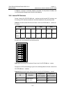
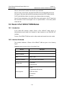
Table 3-21 Correlation between DIP switches of Router 2 and 4-Port CE1/PRI MIM and modules and
E1 interface
Module 2-port 4-port
DIP
switch
S1 S1 S3 S4 S5
E1
interface
Interface
0
Interface
0
Interface
1
Interface
2
Interface
3
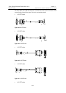
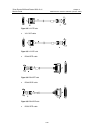
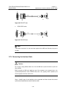
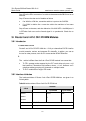
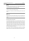
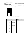
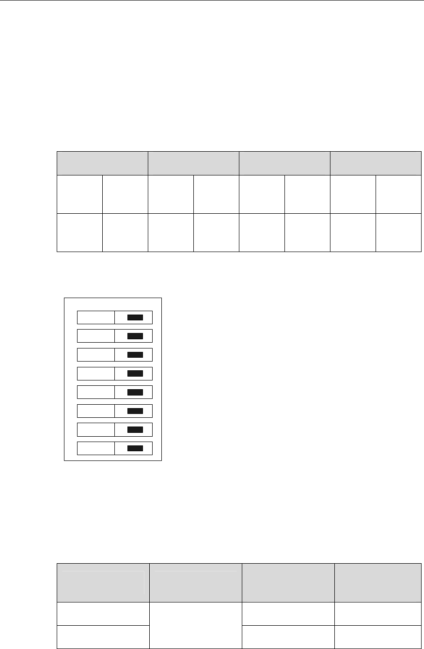
By default, all the DIP switches for Router 2 and 4-Port CE1/PRI MIM and modules
are set to ON, as illustrated in the following figure:
on
1
2
3
4
5
6
7
8
Figure 3-44 Default setting of DIP switches for Router 2 and 4-Port CE1/PRI MIM and modules
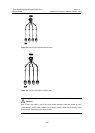
Description of DIP switch settings is given in the following table for Router 2 and 4-Port
CE1/PRI MIM and modules:
Table 3-22 Description of DIP switch settings of Router 2 and 4-Port CE1/PRI MIM and modules
DIP Description
Configuration of
75-ohm impedance
Configuration of
120-ohm impedance
1BIT ON OFF
2BIT
75-ohm/120-ohm
selection switch
ON OFF