


3Com Router 5000 and Router 6000 v2.41
Module Guide
Chapter 3
Multifunctional Interface Modules (Router 5000)
3-20
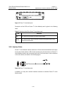
example, PC or router) to a HUB or LAN switch. The cables delivered with the
router are straight-through cables.
z Crossover cable: The wires are crimped in the RJ-45 connectors at both ends in
different orders. The cable is used for connecting two terminal devices (for
example, PC and router). You can make cables as needed.
Note:
In making network cables, shielded cables are preferred for electromagnetic
compatibility sake.
The interface cables in the standard package of cards are straight-through cables.
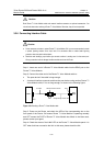
3.5.5 Connecting the Interface Cable
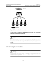
Step 1: Plug one end of the cable to an Ethernet port on the router and another end to
the device to be connected. (For a PC or router, use a straight-through cable; for a
HUB or LAN switch, use a crossover cable.)
Step 2: Power on the router and check the behavior of the LINK LED on the panel: ON
means that a link is present and OFF means that no link is present. In the latter case,
check the line status.
Caution:
Before you connect a port, read its label carefully; a wrong connection can cause damages to the
interface card and even the device.
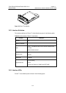
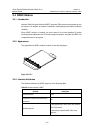
3.6 Router 4-Port Serial MIM Module
3.6.1 Introduction
4-port high-speed sync/async serial interface module (Router 4-Port Serial MIM)
supports both synchronous and asynchronous modes to transmit/receive and handle
data streams at sync/async serial interfaces. The modules also support Data Terminal
Equipment/Data Circuit-terminating Equipment (DTE/DCE) mode when they are in
synchronous operating mode.
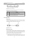
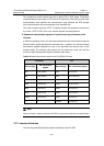
I. Synchronous and asynchronous
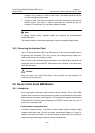
In different operating modes, a sync/async serial interface supports different signal
standards and baud rates. And the maximum transmission distance of signals is
related to the baud rate setting. For the relationships between cable type, baud rate
setting and signal transmission distance, see the following table.