


3Com Router 5000 and Router 6000 v2.41
Module Guide
Chapter 4 Flexible Interface Cards (Router 6000)
4-17
4.6.3 Panel and Interface LEDs
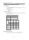
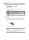
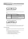
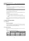
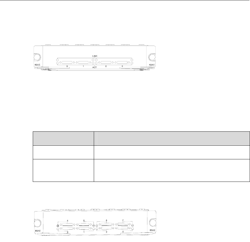
The following figures show the Router 4/8-Port Enhanced Serial FIC panels:
Figure 4-12 Router 4-Port Enhanced Serial FIC panel
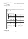
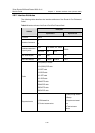
The following table describes the LEDs on the Router 4-Port Enhanced Serial FIC
panel:
Table 4-13 LEDs on the Router 4-Port Enhanced Serial FIC panel
LED Description
LINK OFF means no link is present; ON means a link is present.
ACT
OFF means no data is being transmitted or received. Blinking means
data is being transmitted and/or received.
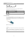
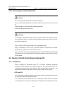
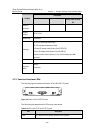
The following figure shows the Router 8-Port Enhanced Serial FIC panel:
Figure 4-13 Router 8-Port Enhanced Serial FIC front panel
On the Router 8-Port Enhanced Serial FIC panel, each link corresponds to a LED. ON
means a link is present; blinking means data is being transmitted and/or received.
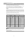
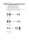
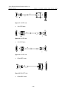
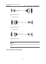
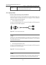
4.6.4 Interface Cable
The FIC-SAE cards use synchronous/asynchronous serial interface cables with DB-28
connectors.
Before connecting an FIC-SAE card, identify the line properties and then select the
proper interface cable from the following ten cable options:
z V.24 (RS232) DTE cable: DB-25 plug at the network end
z V.24 (RS232) DCE cable: DB-25 receptacle at the network end
z V.35 DTE cable: 34PIN plug at the network end
z V.35 DCE cable: 34PIN receptacle at the network end