


Reference
Parameters
Chapter 5
O:\Manuals\E6385A_Amps\Book\Reference.fm
118
Parameters
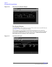
The Test Software uses the entries in the Test Parameters screen to customize testing
and specify serial communications settings.
A special parameter allows the Test Software to run in a demonstration mode, which is
useful for familiarization with the operation of the Test Set without connecting to any
external equipment (see “Demo (Demonstration) Mode” on page 116).
Most parameters may be entered in two ways:
• By loading and running the Test Software and entering all of the information in the
Test Configuration, Base Station Configuration, and Serial Port Configuration
menus. The Test Software automatically changes the test parameter settings to
match the configuration settings.
Parameters that may not be set while the Test Software is running include:
— 1. Adjust TX Power [0=no 1=on fail 2=always]
— 2. GN MSC Command Speed [0=slow 1=fast]
— 4. GN Stop Test if results fail [0=no 1=yes]
— 20. MSC Require CP INH at Ant Port [1=Yes]
— 31. TX Use 230 kHz BW on Data Dev [1=yes]
— 32. ZZZZ Test Demo Mode [0=normal 1=demo]
• By loading the Test Software and selecting Parm Test Parameters on the main
SOFTWARE MENU screen. You may change the settings from the factory defaults.
This section lists the parameters and describes the use of each. For instructions on
changing the parameters and saving the changes on an SRAM card, see “Changing Test
Parameters” on page 103 and “Saving/Deleting a Procedure” on page 109.
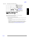
1. Adjust TX Power [0=no 1=on fail 2=always]
Enter the selection to determine the manner in which power output adjustment will
be made.
• If you select 0, the transmitter power output will not be adjusted, irrespective of
the measurement result, and the adjustment power meter will not be displayed.
• If you select 1, the transmitter power output will be adjusted and the power meter
will be displayed if the measured power is outside of the specified pass/fail limits.
Adjust the power output to within the specified pass/fail limits and continue with
testing.
• If you select 2, the transmitter power output will be adjusted and the power meter
will be displayed, irrespective of the measurement result. Adjust the power output
to within the specified pass/fail limits and continue testing.
See "Output Power Adjustment Error" on page 125 and "Output Power Error" on
page 125.