


Performing Tests
TX Gain Test
Chapter 4
77
Performing Tests
TX Gain Test
This test measures the transmit gain of a low-output-power TX device.
CAUTION This test is designed to measure the gain through only low-output-power elements. It is
not designed to measure the LAC gain on a Series II Base Station or power amplifiers on
the other Base Stations.
This test uses the Test Set ANT IN port to measure the output level of the TTU. Input
levels to this port greater than 60 milliwatts (17.8 dBm) might damage the Test Set.
Therefore, the power output of the unit under test must not exceed 60 milliwatts.
Parameters and Specifications Used
The following parameters and specifications are used when running this test. See
Chapter 5, “Reference,” on page 95 for descriptions of the parameters and specifications.
Parameters:
• 17. MSC BTS Type [1=Series II 2=M 3=MM]
Specifications (Pass/Fail Limits):
None used for this test.
Select and Run the Test
Select and run the TX Gain Test as follows:
Step 1. Take the affected radios and the amplifier to be tested out of service. Use a PC to dial
into the MSC and enter the craft shell, or call the MSC and instruct switch personnel as
to which radio to turn off.
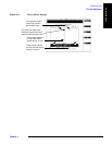
Step 2. From the Lucent AMPS/TDMA Test Main Menu screen, select the Test Selections
field. The Test Software will display the Test Selections Menu screen.
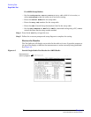
Step 3. Select the TX Gain Test field. The Test Software will display the TX Gain Test screen.
Step 4. Select the Channel Number field. Enter the channel number of the radio by either
turning the knob to the desired number and pressing it, or using the DATA ENTRY keys
to enter the number, then either pressing the knob or the
Enter key to select it.
NOTE The number that you enter in the Channel Number field represents the output frequency
of the device to be tested.
In the case of a PCS Minicell, you must enter a channel number that sets the input
frequency of the TTU to the proper 850-MHz-band frequency to obtain the desired
1900-MHz-band output frequency from the translator.
In the case of an 850-MHz Base Station, the input and output frequencies will be the
same.