


Installation
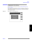
Defining a Frequency Plan
Chapter 2
45
Installation
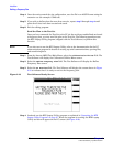
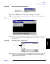
Step 6. Use the Line field to select each line in the plan (which corresponds to individual radios
in the site), and then enter these values for each line:
• ID Number — the Radio ID number (0 to 199)
• Chan Number — the radio channel number (1 to 1023)
• VRAL/CSAC — the Voice RAdio Level (VRAL) for an AMPS radio, or the Control Setup
Attenuation Code (CSAC) for an AMPS Setup radio. Range is 0 to 7.
• Output Power — the power at the TX antenna output from the Antenna Interface
Frame.
• Ant Number — the antenna number for that radio (0 to 6) (see Table 2-1).
• Radio Type — 0=AMPS radio, 1=AMPS Setup radio.
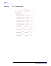
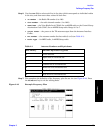
Step 7. This completes the definition of the frequency plan for one site (see Figure 2-16). Press
the
k5 (Return) key to exit the editing mode.
Figure 2-16 Example Frequency Plan
Table 2-1 Antenna Numbers and Equivalents
Ant # Entry Antenna Equivalent (typical)
0Omni antenna
1 Alpha face of a sectored site
2 Beta face of a sectored site
3 Gamma face of a sectored site
4 Delta face of a six-sectored site
5 Epsilon face of a six-sectored site
6 Zeta face of a six-sectored site