


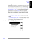


Performing Tests
Single Radio Test
Chapter 4
69
Performing Tests
Parameters and Specifications Used
The following parameters and specifications are used when running this test. See
Chapter 5, “Reference,” on page 95 for descriptions of the parameters and specifications.
Parameters:
• 1. Adjust TX Power [0=no 1=on fail 2=always]
• 3. GN Power Output [0=meas 1=spec 2=blnk]
• 21. TX Antenna Port Cable Loss - when measuring at the antenna foam jumper out of
the Antenna Interface Frame.
• When measuring at the Base Station TX Test Port in the Antenna Interface Frame,
the TX Coupling factor for the associated antenna must be entered. This is done in
parameters 22 through 28.
• 29. TX Output Power
• 30. TX Test Port Cable Loss - when measuring at the Base Station TX Test Port in the
Antenna Interface Frame.
Specifications (Pass/Fail Limits):
This test uses all specifications described in “Specifications (Pass/Fail Limits)” on page
124.
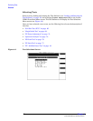
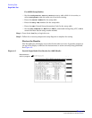
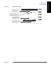
Select and Run the Test
Select and run the Single Radio Test as follows:
Step 1. From the Lucent AMPS Test Main Menu screen, select the Test Selections field. The
Test Software will display the Test Selections Menu screen.
Step 2. Select the Single Radio Test field.
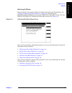
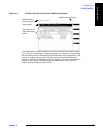
Step 3. Enter information about the radio in the Radio Test Menu screen.
• Enter the Specified Output Power for the radio to be tested. This is the level that
should be present at the output of the Antenna Interface Frame (that would normally
connect to the transmit antenna feed line).
• Enter the Cell Site Number for the site.
• Enter the Antenna Number for the antenna connected to the radio.
• Select the Radio Type from the Choices: list: AMPS or AMPS Setup.
For AMPS Radios:
— Enter the Channel Number for the radio.
— Enter the Radio ID# (number) for the radio.
— Enter the VRAL (Voice RAdio Level) for the radio.
—Set the Send Commands to MSC field to YES for automated testing using a PC, or NO to
control the Base Station using another method.