VLAN Management
Page 9-20
Example of System
With Tagging
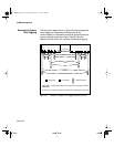
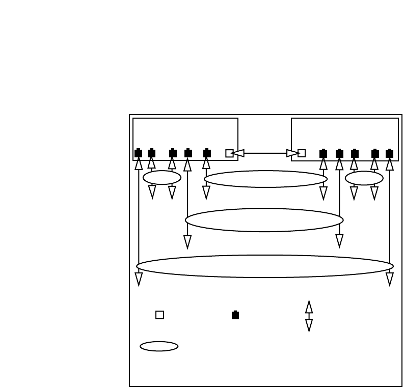
The two-switch system shown in Figure 9-3 demonstrates the
use of tagging to create some VLAN groups that can
communicate with one another, and other groups that cannot
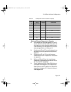
communicate. By studying the figure, Table 9-4, and the
descriptions that follow, you can learn the effects of tagging.
Figure 9-3 Example of a system with tagged (expansion) ports
SWITCH 1
SWITCH 2
6 5 4 3 2 1
1 2 3 4 5 6
V4 Seg
V4 Seg
V1, V5, V10
Vi Seg
V5 Seg
V10 Seg
E1
E2
E3 E4
E5
E6
E7
E8E9
E10
E11
= Tagged Port = Normal Port = Ethernet Segment
= Logical representation of a VLAN group; not a physical connection
E1, E2, E3, etc. are Ethernet Segments to which the corresponding port is connected
6216M Book Page 20 Wednesday, January 27, 1999 5:26 PM


