Installation
Page 2-8
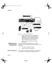
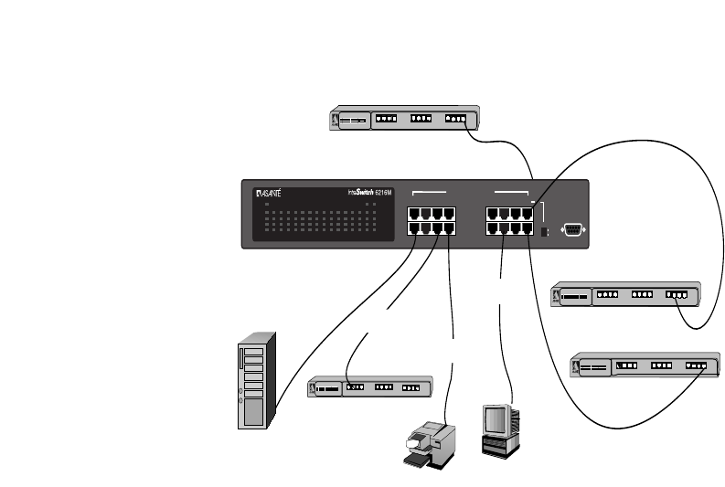
Figure 2-2 IntraSwitch Cabling Scenarios
∆ Note: Pressing the Uplink switch toggles the
usage of port 16 from normal to uplink or vice
versa. This uplink feature is available only for
regular RJ-45 port, and not for MII ports. When
port 16 is used for uplink, the connection
between port 16 to standard hub is straight-
through cable.
Configuring for
Management
To use the IntraSwitch as a managed switch, it must be
configured with an IP address. This can be accomplished in one
of two ways:
❏ automatically using BootP (default)
❏ manually via the unit’s Console port
BootP Configuration The IntraSwitch is shipped with BootP support. BootP allows
the IntraSwitch to be automatically configured with an IP
1357
2468
9111315
10 12 14 16
Switched 10/100Mbps Ports
Console
Uplink
or
Normal
Uplink
12345678910111213141516
Power
100Mbps
FDP
Data
Link
MII 1 MII 2
100Base-TX
Server
Network
Station
Repeater/Hub — Standard Port
1
2
3
4
5
6
7
8
100BASE-TX Ports
AsantéFAST 100 Hub
4
3
2
1
5
678
Col
Pwr
9
10
11
12
Partition
Link/Receive
9
10
11
12
Repeater/Hub — STANDARD Port
1
2
3
4
5
6
7
8
9
10
11
12
100BASE-TX Ports
AsantéFAST 100 Hub
4
3
2
1
5
678
Col
Pwr
9
10
11
12
Partition
Link/Receive
straight-through cable
(100m max. length)
Printer
Repeater/Hub — UPLINK Port
1
2
3
4
5
6
7
8
9
10
11
12
100BASE-TX Ports
AsantéFAST 100 Hub
4
3
2
1
5
678
Col
Pwr
9
10
11
12
Partition
Link/Receive
straight-through cable
(100m max. length)
straight-through cable
(100m max. length)
cross-over cable
(100m max. length)
straight-through cable
(100m max. length)
Port 16 in Uplink mode can
be connected to hub using
straight-through cable
(100m max. length)
from port 16 (Uplink)
Repeater/Hub — UPLINK Port
1
2
3
4
5
6
7
8
9
10
11
12
100BASE-TX Ports
AsantéFAST 100 Hub
4
3
2
1
5
678
Col
Pwr
9
10
11
12
Partition
Link/Receive
from MII port
on rear panel
MII connection
must be fibre
(2km max length)
6216M Book Page 8 Wednesday, January 27, 1999 5:26 PM


