


INTEGRUS | Installation and User Instructions | System description and planning en | 4
Bosch Security Systems | 2005-04 | 3122 475 22015en
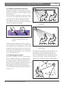
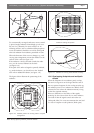
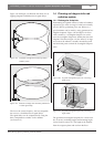
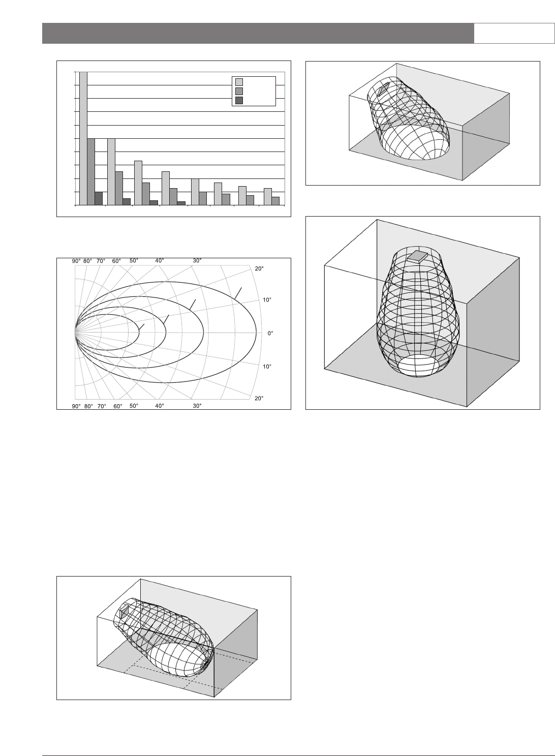
The cross section of the 3-dimensional radiation pat-
tern with the floor of the conference venue is known as
the footprint (the white area in figure 1.7 to figure 1.9).
This is the floor area in which the direct signal is
strong enough to ensure proper reception, when the
receiver is directed towards the radiator. As shown, the
size and position of the footprint depends on the
mounting height and angle of the radiator.
1.3.3 Ambient lighting
The Integrus system is practically immune for the
effect of ambient lighting. Fluorescent lamps (with or
without electronic ballast or dimming facility), such as
TL lamps or energy saving lamps give no problems
with the Integrus system. Also sunlight and artificial
lighting with incandescent or halogen lamps up to 1000
lux give no problems with the Integrus system.
When high levels of artificial lighting with incandes-
cent or halogen lamps, such as spotlights or stage light-
ing are applied, you should directly point a radiator at
the receivers in order to ensure reliable transmission.
For venues containing large, unscreened windows, you
must plan on using additional radiators.
For events taking place in the open air a site test will
be required in order to determine the required amount
of radiators. With sufficient radiators installed, the
receivers will work without errors, even in bright sun-
light.
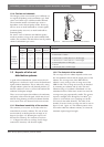
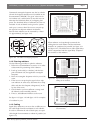
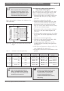
0
200
400
600
800
1000
1200
1400
1600
1800
2000
12345678
LBB 4511/00
LBB 4512/00
LBB 3410/05
m
2
Figure 1.5
Total coverage area of LBB 3410/05, LBB 4511/00
and
LBB 4512/00 for 1 to 8 carriers
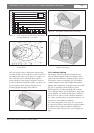
Figure 1.6 Polar diagram of the radiation pattern for 1, 2, 4
and 8 carriers
1
8
2
4
Figure 1.7 The radiator mounted at 15° to the ceiling
Figure 1.8 The radiator mounted at 45° to the ceiling
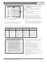
Figure 1.9 The radiator mounted perpendicular
(at 90°) to the ceiling