


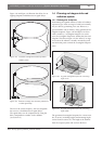
Figure 1.27 and table 1.2 illustrate the calculation of
the signal delays and the delay switch positions.
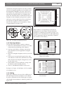
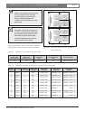
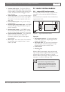
1.5.2 System with two or more transmitters
in one room
When radiators in one multi purpose room are con-
nected to two transmitters, an extra signal delay is
added by:
• Transmission from master transmitter to slave trans-
mitter (cable signal delay).
• Transmission through the slave transmitter.
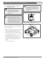
Use the following procedure to determine the delay
switch positions in a master-slave configuration:
1. Calculate the cable signal delay for each radiator,
using the procedures for a system with one trans-
mitter.
2. Calculate the signal delay of the cable between the
master and the slave transmitter in the same way as
for cables between a transmitter and a radiator.
3. Add to the cable signal delay of the cable between
the master and the slave, the delay of the slave
transmitter itself: 33 ns. This gives the master-to-
slave signal delay.
4. Add the master-to-slave signal delay to each radia-
tor connected to the slave transmitter.
5. Determine the maximum signal delay.
6. Calculate for each radiator the signal delay differ-
ence with the maximum signal delay.
7. Divide the signal delay difference by 33. The
rounded off figure is the signal delay switch posi-
tion for that radiator.
8. Add delay switch positions to radiators under a bal-
cony, if applicable (see section 1.5.3)
9. Set the delay switches to the calculated delay switch
positions.
INTEGRUS | Installation and User Instructions | System description and planning en | 11
Bosch Security Systems | 2005-04 | 3122 475 22015en
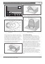
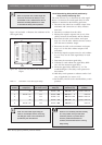
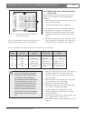
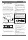
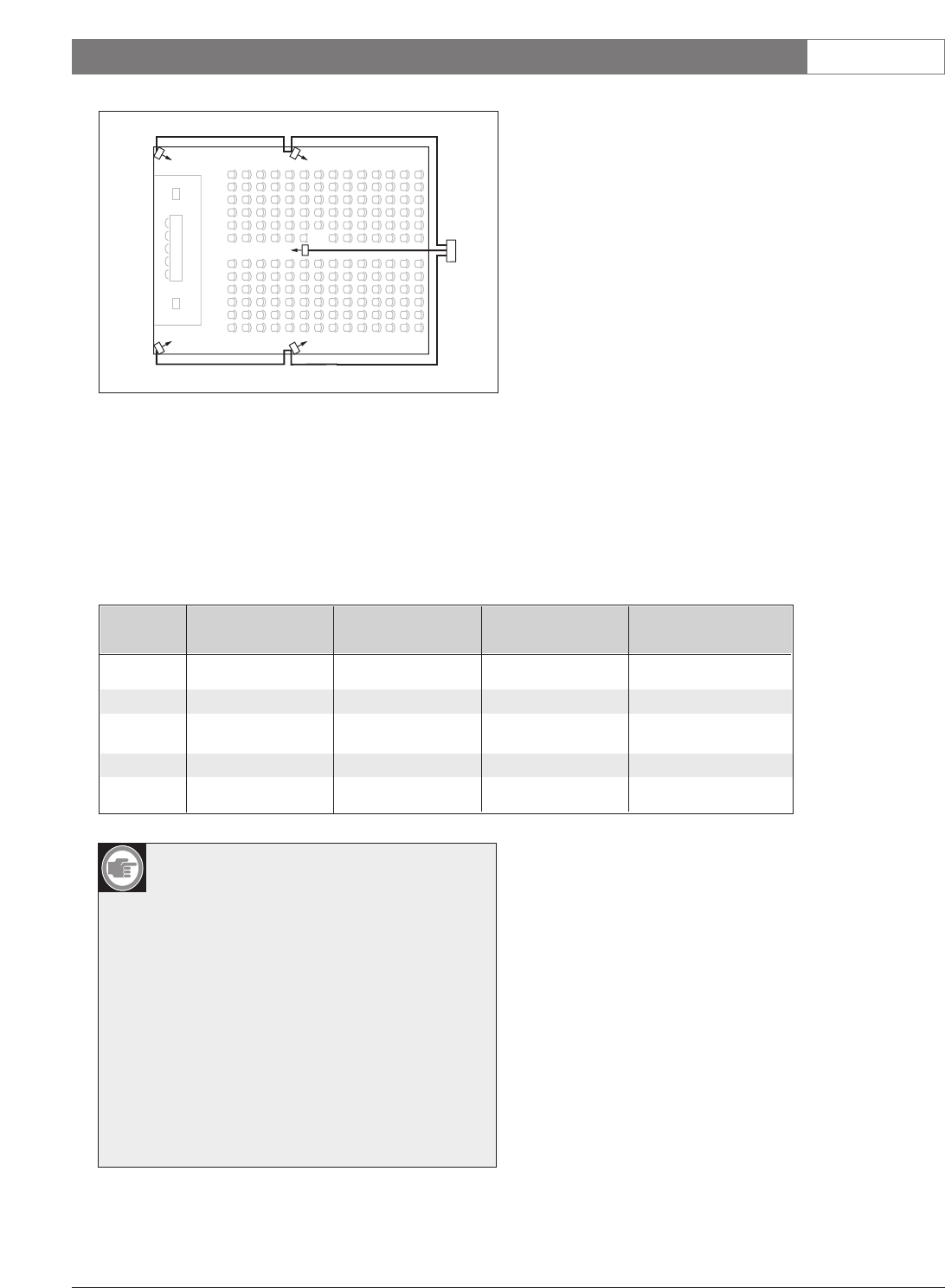
Table 1.2 Calculation of the delay switch positions of a system with one transmitter
584 ns 350 ns
563 ns 339 ns
R2
R5 R4
237 ns
R1
R3
Figure 1.27 System with five radiators and measured
impulse response times
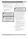
Note: The calculated delay switch posi-
tions based on impulse response time
can differ from the calculated delay
switch positions based on cable lengths.
This is caused by the accuracy of the
measurements and the accuracy of the
cable signal delay factor per meter as
specified by the manufacturer of the
cable. If the impulse response time is
measured correctly, the calculated delay
switch positions will be the most accu-
rate.
Radiator Impulse response Cable signal Signal delay Delay switch
number time [ns] delay [ns] difference [ns] position
1 350 350/2 = 175 292-175 = 117 117/33 = 3.54 = 4
2 584 584/2 = 292 292-292 = 0 0/33 = 0
3 237 237/2 = 118 292-118 = 174 174/33 = 5.27 = 5
4 339 339/2 = 169 292-169 = 123 123/33 = 3.73 = 4
5 563 573/2 = 281 292-281 = 11 11/33 = 0.33 = 0