


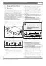
INTEGRUS | Installation and User Instructions | Integrus Transmitters en | 19
Bosch Security Systems | 2005-04 | 3122 475 22015en
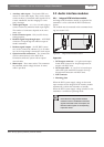
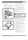
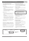
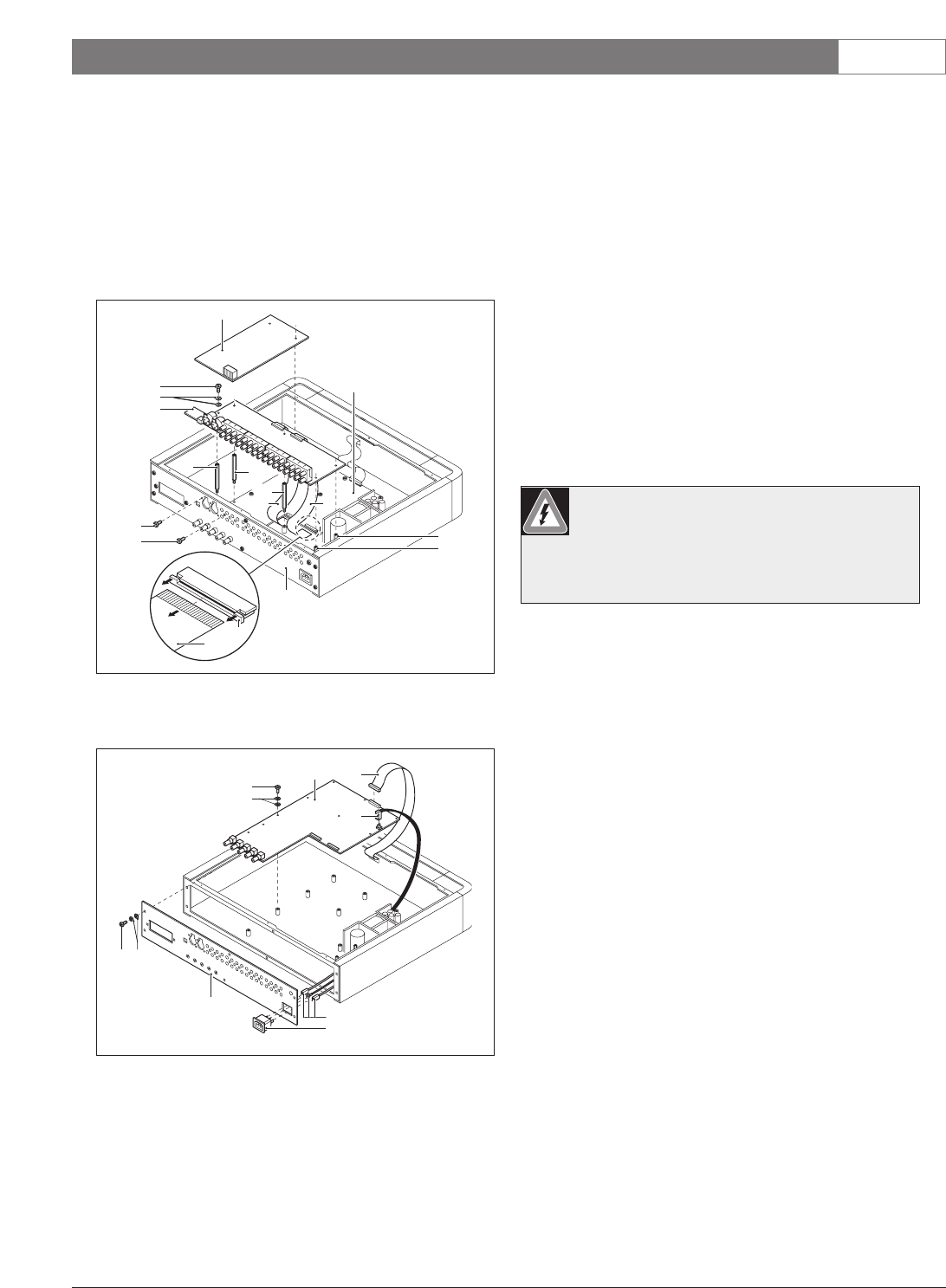
8. Remove the rear panel (4):
• Loosen the screws (16). Do not lose the (spring)
washers (17).
• Pull the connectors (18) of the mains inlet wires
and the earth wire out of the mains socket (19).
• Detach the mains socket from the rear panel.
The mains socket is snapped into the rear panel.
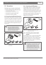
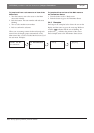
2.2.3.2 Installation of the INT-TXK
Follow the instructions below to install the INT-TXK.
The numbers refer to figures 2.9 and 2.10.
1. If the LBB4502/xx transmitter is missing a stud to
mount the new main PCB (2) of the INT-TXK,
paste the glue stud (1) from the upgrade kit to the
bottom of the transmitter. See inset in figure 2.9 for
the recommended pasting position.
2. Click the mains socket (3) in position in the new
rear panel (4).
3. Fit the connectors (5) of the mains inlet wires
(5A – brown, 5B – blue) and the earth wire (5C)
on the pins of the mains socket.
4. Mount the rear panel using the screws (6) and the
(spring) washers (7).
5. Install the main PCB (2) using the screws (8) and
the (spring) washers (9). If the LBB4502/xx trans-
mitter is provided with a stud to mount the main
PCB, use the extra screw from the upgrade kit.
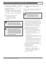
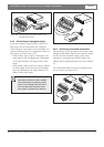
6. On the new main PCB:
• Fasten the user interface cable (10).
• Fasten the power supply connector (11).
7. Mount the three distance studs (12A, 12B and 12C)
of the analogue input/output PCB through the ori-
fices in the new main PCB.
8. Mount the analogue input/output PCB (13):
• Place the analogue input/output PCB on its dis-
tance studs (12).
• Fit the screws (14) with the (spring) washers (15).
• Carefully give the screws a few turns. Do not
yet tighten the screws.
• Fit and tighten the screws (16) at the XLR con-
nectors on the rear panel.
• Fit and tighten the screws (17) between the cinch
plugs on the rear panel.
• Tighten the screws (14) of the distance studs
(12).
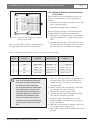
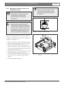
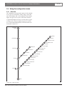
Figure 2.8 Removing the main PCB and the rear panel
(steps 6 - 8)
9
14
13
12
19
15
16
4
17
18
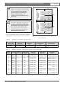
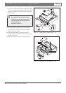
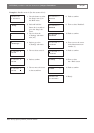
Figure 2.7 Removing the main PCB and the rear panel
(steps 1 - 5)
1
9
6
2
5
3
7
7
4
11
7A
7C
10 10
10
7B
8
Warning: Pay attention to the correct
position of the mains inlet wires.
See inset in figure 2.9.