


INTEGRUS | Installation and User Instructions | Integrus Transmitters en | 18
Bosch Security Systems | 2005-04 | 3122 475 22015en
2.2.3 Upgrading an LBB4502/xx to an INT-TX
To upgrade an LBB4502/xx to an INT-TX the follow-
ing upgrade kits are available:
• INT-TXK04: 4 channel transmitter upgrade kit
• INT-TXK08: 8 channel transmitter upgrade kit
• INT-TXK16: 16 channel transmitter upgrade kit
• INT-TXK32: 32 channel transmitter upgrade kit
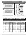
Each kit comprises the following items:
• 1 (type dependent) rear panel
• 1 (type dependent) main PCB
• 1 extra screw for the main PCB
• 1 glue stud
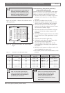
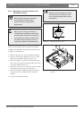
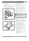
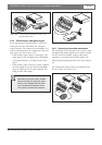
2.2.3.1 Removing the main PCB and the rear
panel
Follow the instructions below to remove the main PCB
and the rear panel. The numbers refer to figure 2.7
and figure 2.8.
1. Remove the top cover of the transmitter housing.
2. If the transmitter contains an interface module (1):
Remove the interface module proceeding in reverse
order of mounting. The mounting instructions can be
found in section 2.2.2. Note that the distance studs
of the transmitter module can remain in place.
3. If the transmitter does not contain an interface
module: Remove the interface module slot cover
proceeding as described in section 2.2.2.
4. Remove the analogue input/output PCB (2):
• Loosen the screws (3) between the cinch plugs
on the rear panel (4). The number of screws
depends on the transmitter type.
• Loosen the screws (5) at the XLR connectors
on the rear panel.
• Loosen the screws (6) of the distance studs (7) of
the analogue input/output PCB. Do not lose the
(spring) washers (8).
• On the main PCB (9) detach the flexible cables
(10) to the analogue input/output PCB. To this
end release the catches (11) on both sides and
pull out the flexible cable. See inset in figure 2.7.
• Remove the analogue input/output PCB.
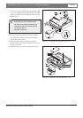
5. Remove three distance studs (7A, 7B and 7C) of the
analogue input/output PCB.
6. On the main PCB (9):
• Detach the user interface cable (12).
• Detach the power supply connector (13).
• Loosen the screws (14) of the distance studs.
Do not lose the (spring) washers (15).
7. Remove the main PCB.
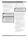
Warning: Before opening the transmitter
housing, make sure that the mains power
and all other connections are disconnected.
Warning: ICs and many other electronic
components are susceptible to electrostatic
discharge (ESD). Take preventive measures
when handling the PCBs. Keep the PCBs as
long as possible in their protective packing.
Wear an anti-ESD bracelet.
Note: The upgrade kits do not contain
new fixing materials. Therefore make
sure to keep all screws and washers.