


INTEGRUS | Installation and User Instructions | System description and planning en | 7
Bosch Security Systems | 2005-04 | 3122 475 22015en
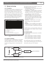
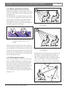
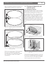
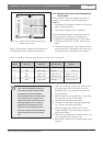
Figure 1.18 and figure 1.19 illustrate the effect of over-
lapping footprints and differences in signal delays.
The lower the carrier frequency, the less susceptible
the receiver is for differences in signal delays.
The signal delays can be compensated by using the
delay compensation switches on the radiators
(see section 1.5).
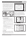
1.4 Planning an Integrus infra-red
radiation system
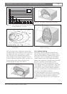
1.4.1 Rectangular footprints
Determining the optimal number of infra-red radiators
required to give 100% coverage of a hall can normally
only be done by performing a site test. However, a
good estimation can be made by using ‘guaranteed rec-
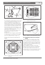
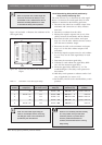
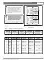
tangular footprints’. Figure 1.20 and figure 1.21 show
what is meant by a rectangular footprint. As can be
seen, the rectangular footprint is smaller than the total
footprint. Note that in figure 1.21 the ‘offset’ X is nega-
tive because the radiator is actually mounted beyond
the horizontal point at which the rectangular footprint
starts.
The guaranteed rectangular footprints for various num-
ber of carriers, mounting heights and mounting angles
can be found in section 7.6. The height is the distance
from the reception plane and not from the floor.
Figure 1.18 Increased coverage area caused by added
radiation power
Figure 1.19 Reduced coverage area caused by differences
in cable signal delay
W
H
L
X
Figure 1.20 A typical rectangular footprint for a mounting
angle of 15°
Figure 1.21 A typical rectangular footprint for a mounting
angle of 90°
X
W
H
L