


INTEGRUS | Installation and User Instructions | Integrus Radiators en | 47
Bosch Security Systems | 2005-04 | 3122 475 22015en
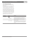
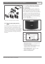
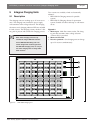
The following are found on the radiator printed circuit
board: (Figure 3.13):
Figure 3.13 LBB 3410/05 Radiator (PCB)
5. Green LED - indicates that the radiator is switched
on and is receiving carrier waves from the transmitter.
6. Red LED - indicates that the radiator output is 70%
or less of the normal output level.
Mains voltage selection of 115 V or 230 V is internally
selectable. On delivery the radiator is set for 230 Va.c.
operation. To alter the mains voltage selection for the
LBB 3410/05 radiators, it is necessary to solder two
leads to contacts on the printed circuit board (PCB)
inside the radiator. To locate the PCB, remove the four
securing screws at the rear of the radiator and remove
the unit from its housing. Remove the PCB from its
mounting by removing the PCB’s six securing screws
and the small connector X1 (figure 3.13). To select
115 V operation, solder two small leads, one connect-
ing X4 to X6 and one connecting X5 to X7. Then
remove the small SMD resistor R3. When this is com-
pleted replace fuse F1 (160 mA) with a fuse rated at
350 mA.
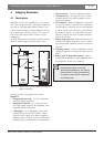
Limitations:
• Not more than the first 4 carriers can be transmit-
ted.
• Not more than 100 m cable length from transmitter
to last radiator.
• Directly connection of the radiators to the transmit-
ter with equal cable length. In loop-through con-
nection, the total cable length from the first to the
last radiator may not exceed 5 meters. Reason:
there are no facilities on this radiator for compen-
sating the cable signal delay.
• Don’t use this radiator in combination with LBB
4511/00 and LBB 4512/00 radiators in one system,
as the internal signal delay of these radiators are
different.
• No automatic cable termination: the termination
plug has to be connected to the last radiator in a
trunk.
• No communication of the radiator status to the
transmitter.
• Using this radiator at 105 to 125 V requires internal
adjustments.
3.2.2 Radiator Status Indication
When the radiator is transmitting, a green LED mount-
ed internally on a printed circuit board illuminates. If
there is a failure in the radiator, a red LED illuminates
on the printed circuit board.
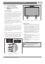
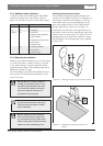
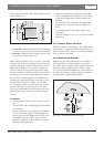
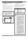
3.2.3 Mounting the Radiator
Radiators in permanent installations can be fixed to a
wall, hung under a ceiling or balcony or secured to
any sturdy material using the unit’s built-in bracket and
mounting adaptor supplied with the radiator (figure
3.14). In non-permanent installations, a floor stand can
be used. The mounting adaptor enables the radiator to
be positioned for optimum performance.
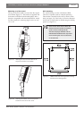
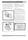
Figure 3.14 LBB 3410/05 Radiator Mounting
6
5