


INTEGRUS | Installation and User Instructions | System description and planning en | 13
Bosch Security Systems | 2005-04 | 3122 475 22015en
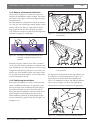
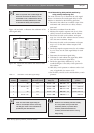
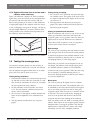
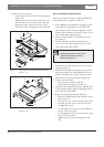
1.5.3 System with more than 4 carriers and a
radiator under a balcony
Figure 1.29 illustrates a situation in which a radiation
signal delay occurs and which can be compensated for.
For systems with more than four carriers, add one
delay switch position per 10 meter (33 feet) difference
in signal path length to the radiators which are closest
to the overlapping coverage area. In figure 1.29 the sig-
nal path length difference is 12 meter. Add one delay
switch position to the calculated switch position(s) for
the radiator(s) under the balcony.
1.6 Testing the coverage area
An extensive reception quality test must be done to
make sure that the whole area is covered with IR radi-
ation of adequate strength and that there are no black
spots. Such a test can be done in two ways:
Testing during installation
1. Check that all radiators are connected and powered
up and that no loose cables are connected to a radi-
ator. Switch the transmitter off and on to re-initialise
the auto equalisation of the radiators.
2. Set the transmitter in the Test-mode (see section
2.5.7). For each channel, a different test tone fre-
quency will be transmitted.
3. Set a receiver on the highest available channel and
listen via the headphones to the transmitted test
tone.
4. Test all positions and directions (see next para-
graph).
Testing during a meeting
1. Set a receiver in the Test-mode and select the high-
est available carrier. The quality of the received car-
rier signal is indicated on the display of the receiver
(see section 4.3).
2. Test all positions and directions (see next para-
graph). The quality indication should be between
00 and 39 (good reception).
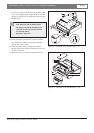
Testing all positions and directions
With the transmitter and receiver in one of the two test
modes, go around the conference hall and test the
reception quality at every position where the infra-red
signals must be received. When an area is detected
where there is bad reception or even no reception at
all, three main causes must be considered:
Bad coverage
The receiver can not pick-up infra-red radiation of ade-
quate strength. This can be because the tested position
is outside the footprint of the installed radiators or the
radiation is blocked by obstacles such as a column, an
overhanging balcony or other large objects.
Check that you used the correct footprints for the sys-
tem design, that radiators with enough output power
are installed and that a radiator is not accidentally
switched to half power operation. When the bad recep-
tion is caused by a blocked radiation path, try to
remove the blocking obstacle or add an extra radiator
to cover the shaded area.
Black spots
The receiver picks-up IR signals from two radiators
which cancel out each other. The multipath effect can
be identified by the observation that the bad reception
only occurs along a specific line and/or when good
reception returns when the receiver is rotated to anoth-
er direction. This can be confirmed by keeping the
receiver in the position and direction with the bad
reception and then either shading-off the radiation
from one radiator with your hand or switching off one
radiator. If this improves the reception quality, then the
multipath effect is causing the problem. Note that IR
radiation that is reflected from a surface with a high
reflectabiliy can also cause multipath problems.
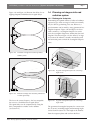
Figure 1.29
Radiation path length difference for two radiators
16m
4m