


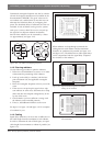
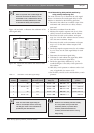
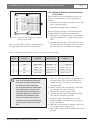
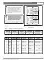
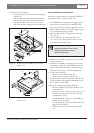

Figure 1.28, table 1.1, table 1.3 and table 1.4 illustrate
the calculation of the extra master-slave signal delay.
INTEGRUS | Installation and User Instructions | System description and planning en | 12
Bosch Security Systems | 2005-04 | 3122 475 22015en
Table 1.3 Calculation of the master-to-slave signal delays
Cable length Cable Cable Signal delay Master-to-slave
master-slave signal delay signal delay slave transmitter signal delay [ns]
transmitter [m] per meter [ns/m] [ns] [ns]
50 5.6 50 x 5.6 = 280 33 280 + 33 = 313
Table 1.4 Calculation of the delay switch positions of a system with two transmitters
R2
R1
R4
R6
R9
20m
R7
R5
R10
Tx2
R8
R3 Tx1
20m
30m
20m
50m
30m20m
20m
30m
30m
20m
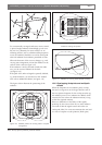
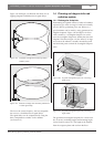
Figure 1.28 System with master and slave transmitter in
multi purpose room
Caution: Turn the delay switches carefully
to a new position until you feel that it
clicks into position, to prevent that a
switch is positioned between two
numbers, which would result in a wrong
delay setting.
Note: When a master-slave configuration
is used for rooms which are always sepa-
rated, the delay switch positions can be
determined per system and the delay
caused by transmission from master to
slave transmitter can be ignored.
Radiator Transmitter Master-to- Cable signal Total signal Signal delay Delay switch
number slave signal delay [ns] delay [ns] difference position
1 Master 0 168 0+168 = 168 593-168 = 425 425/33 = 12.88 = 13
2 Master 0 280 0+280 = 280 593-280 = 313 313/33 = 9.48 = 9
3 Master 0 112 0+112 = 112 593-112 = 481 481/33 = 14.58 = 15
4 Master 0 168 0+168 = 168 593-168 = 425 425/33 = 12.88 = 13
5 Master 0 280 0+280 = 280 593-280 = 313 313/33 = 9.48 = 9
6 Slave 313 168 313+168 = 481 593-481 = 112 112/33 = 3.39 = 3
7 Slave 313 280 313+280 = 593 593-593 = 0 0/33 = 0
8 Slave 313 112 313+112 = 425 593-425 = 168 168/33 = 5.09 = 5
9 Slave 313 168 313+168 = 481 593-481 = 112 112/33 = 3.39 = 3
10 Slave 313 280 313+280 = 593 593-593 = 0 0/33 = 0