


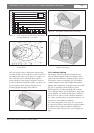
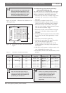

Figure 1.26 and table 1.1 illustrate the calculation of the
cable signal delay.
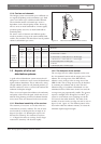
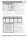
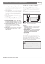
1.5.1.2 Determining delay switch positions by
using a delay measuring tool
The most accurate way to determine the cable signal
delays is to measure the actual signal delay for each
radiator as described in the following procedure:
1. Disconnect the cable from a radiator output of the
transmitter and connect this to a delay measure-
ment tool.
2. Disconnect a radiator from this cable.
3. Measure the impulse response time (in ns) of the
cable(s) between the transmitter and the radiator.
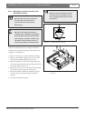
4. Reconnect the cable to the radiator and repeat
steps 2 to 4 for the other radiators that are connect-
ed to the same transmitter output.
5. Reconnect the cable to the transmitter and repeat
step 1 to 5 for the other radiator outputs of the
transmitter.
6. Divide the impulse response times for each radiator
by two. These are the cable signal delays for each
radiator.
7. Determine the maximum signal delay.
8. Calculate for each radiator the signal delay differ-
ence with the maximum signal delay.
9. Divide the signal delay difference by 33. The
rounded off figure is the delay switch position for
that radiator.
10. Add delay switch positions to radiators under a bal-
cony, if applicable (see section 1.5.3)
11. Set the delay switches to the calculated delay switch
positions.
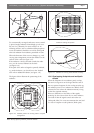
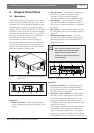
Figure 1.26 System with five radiators and measured cable
lengths
INTEGRUS | Installation and User Instructions | System description and planning en | 10
Bosch Security Systems | 2005-04 | 3122 475 22015en
20m
20m
30m
30m
R2
R5 R4
R3
R1
20m
Table 1.1 Calculation of the cable signal delays
Radiator Total cable Cable signal delay Cable signal Signal delay Delay switch
number length [m] per meter [ns/m] delay [ns] difference [ns] position
1 30 5.6 30*5.6 = 168 280-168 = 112 112/33 = 3.39 = 3
2 30+20 = 50 5.6 50*5.6 = 280 280-280 = 0 0/33 = 0
3 20 5.6 20*5.6 = 112 280-112 = 168 168/33 = 5.09 = 5
4 30 5.6 30*5.6 = 168 280-168 = 112 112/33 = 3.39 = 3
5 30+20 = 50 5.6 50*5.6 = 280 280-280 = 0 0/33 = 0
Note: The used cable signal delay per
meter is an example. Use the actual sig-
nal delay per meter in this calculation as
specified by the manufacturer.
Caution: Turn the delay switches carefully
to a new position until you feel that it
clicks into position, to prevent that a
switch is positioned between two
numbers, which would result in a wrong
delay setting.
Note: For systems with a cable length dif-
ference of more than 50 meters, it is rec-
ommended to use a measurement tool to
determine the delay differences in order
to calculate the delay switch positions.