


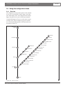
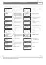
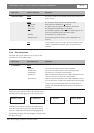
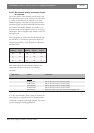

2.5.4 View fault status
The fault status of the radiators can be seen in the
second screen of the Main menu:
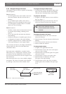
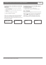
When the system detects a failure for the first time, a
flashing fault message pops-up on any menu screen:
or
or
Push the menu button to remove the fault message
from the screen and to go back to the menu screen
that was visible before the fault message popped-up.
The flashing message will also disappear when the fault
has been resolved.
INTEGRUS | Installation and User Instructions | Integrus Transmitters en | 31
Bosch Security Systems | 2005-04 | 3122 475 22015en
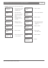
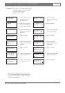
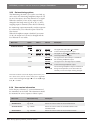
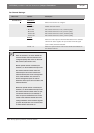
Menu Items Value (read only) Description
1 Fault Status F
ault:
- No Faults The connected radiators function without problems.
- Radiator Fault One of the connected radiators is not functioning properly.
- No Radiators No radiators are connected to the transmitter.
- No Network When the Network Mode (see section 2.5.8) is Enabled, this fault
is shown when there is a fault in the optical network.
- Network Error When the Network Mode (see section 2.5.8) is Disabled, this fault
is shown when there is a fault in the optical network. This message
usually occurs when the Network Mode (see section 2.5.8) is
disabled, and a DCN Next Generation CCU is connected to the
transmitter.
Radiator Fault
No Radiators
No Network
Network Error
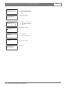
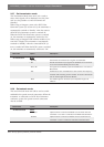
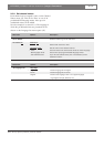
Menu Items Options (read only) Description
Transmitter Status Name
The first line shows the user defined name of the transmitter (see
section 2.5.16).
Mode:
The second line shows the actual transmission mode:
- nn
Channels Audio signals are distributed on nn channels.
- Aux to All The signal on the Aux. inputs is distributed on all channels.
- nn
Ch. Test The test signals are distributed on nn
channels.
- Slave The transmitter operates in slave-mode: the radiator signal on the
slave input is looped-through to all radiator outputs.
- Standby The transmitter is in stand by mode.
- Emergency Call An emergency signal from the Aux. inputs is distributed to all
channels.
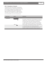
DCN
The text ‘DCN’ is shown at the right side of the second line when
a DCN or a DCN Next Generation system is connected to the
transmitter.
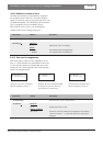
or or