


INTEGRUS | Installation and User Instructions | Integrus Transmitters en | 15
Bosch Security Systems | 2005-04 | 3122 475 22015en
2 Integrus Transmitters
2.1 Description
The transmitter is the central element of the Integrus
system. It accepts asymmetrical audio sources from a
maximum of 32 external channels (dependent on the
transmitter type) and can be used with the Digital
Congress Network (DCN) and DCN Next Generation
conference systems. It can also be used with analogue
discussion and interpretation systems (e.g. CCS 800
with up to 12 interpreter desks), or as a stand-alone
system distributing external audio sources.
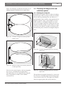
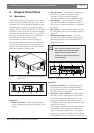
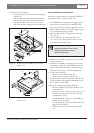
The transmitter is suitable for either table-top or
19-inch rack-mounted use. Four feet (for table top use)
and two mounting brackets (for rack mounting) are
supplied. The mounting brackets can also be used to
mount the transmitter to a flat surface.
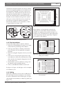
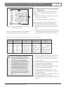
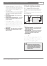
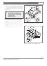
Figure 2.2:
1. Mains on/off switch – After switching the mains
on, the transmitter starts up and the display (3) will
light-up.
2. Mini IR-radiator – Four IREDs, transmitting the
same infra-red signal as the radiator output.
This can be used for monitoring purposes.
They can be disabled via the configuration menu.
3. Menu display – A 2x16 character LCD-display
gives information about the transmitter status. It is
also used as a an interactive display for configuring
the system.
4. Menu button – A turn-and-push button to operate
the configuration software in combination with the
display (3).
5. Monitoring headphone output – A 3.5 mm
(0.14 inch) jack socket to connect a headphone for
monitoring purposes. It can be disabled via the
configuration menu.
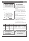
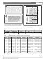
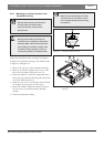
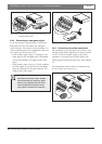
Figure 2.3:
1. Interface module slot – An optional audio inter-
face module can be mounted in the transmitter
housing. Its connectors are accessible via an open-
ing at the back of the transmitter.
2. Emergency switch connector – A terminal block
socket for a single, ‘normally open’ switch. When
the switch is closed, the audio signal on the Aux-
right input is distributed on all output channels,
overriding all other audio inputs. A matching cable
connector is provided.
The emergency contact does not function when the
network mode of the transmitter is enabled (see
section 2.5.8) and it cannot connect to the optical
network (e.g. because the control unit of the DCN
Next Generation conference system is switched off).
Figure 2.1 Transmitter with optional mounting brackets and
table-top feet
32 4 51
Figure 2.2 Transmitter, front view
Note: The mini IR-radiator and the head-
phone output can also be permanently
disabled by removing two resistors.
Consult your regular service contact for
more information.
135791113151719212325272931
024
456231
81012141618202224262830
Network
12
1 2
6
97
53
8
4
Figure 2.3 Transmitter, rear view