


INTEGRUS | Installation and User Instructions | Integrus Radiators en | 42
Bosch Security Systems | 2005-04 | 3122 475 22015en
3 Integrus Radiators
3.1 Medium and High Power
Radiators
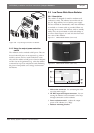
3.1.1 Description
These units accept the carrier signals generated by the
transmitter and emit infra-red radiation carrying up to
32 audio distribution channels. They are connected to
one or more of the four HF BNC outputs of the IR
transmitter. A maximum of 30 radiators can be con-
nected to each of these outputs by means of loop-
through connections.
The LBB 4511/00 has an infra-red output of 16 Wpp,
while the LBB 4512/00 has an infra-red output of
32 Wpp. Both have an automatic mains power voltage
selection and are switched on automatically when the
transmitter is switched on.
The attenuation of the signal by the cable is equalised
automatically by the radiator. When the radiator is sup-
plied with power and the transmitter is switched on,
the radiator initialises the equalisation. The red LEDs
flash for a brief period of time to indicate that the ini-
tialisation is in progress.
When not receiving carrier waves, the radiators switch
to standby mode. There is also a temperature protec-
tion mode which automatically switches the radiators
from full to half power or from half power to stand-by
if the temperature of the IREDs becomes too high.
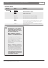
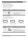
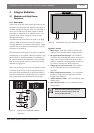
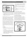
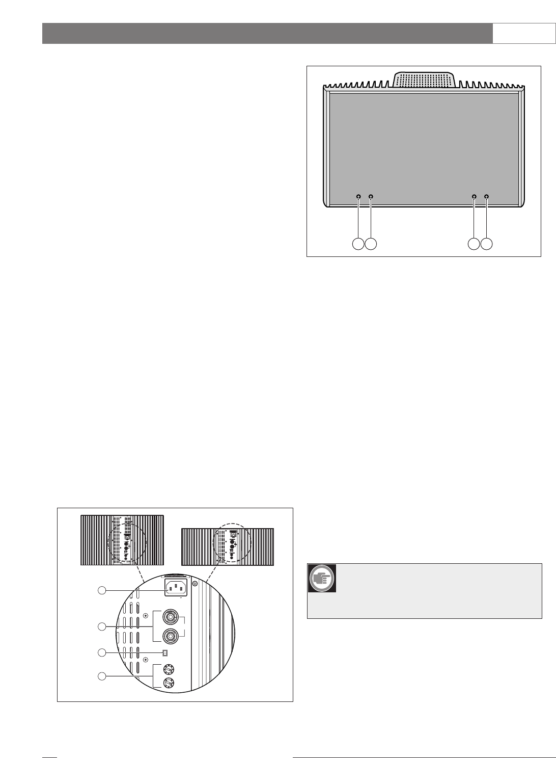
Figure 3.1 and 3.2
1. Mains input - Male Euro mains connector. The
radiators have automatic mains voltage selection.
2. IR signal input/loop-through - Two HF BNC
connectors for connecting the radiator to the trans-
mitter and for loop-through connection to other
radiators. Automatic cable termination is achieved
by a built-in switch in the BNC connectors.
3. Output power selection switch - The radiators
can be switched between full- and half-power
operation.
4. Delay compensation switches - Two 10-position
switches to compensate for differences in cable
lengths to the radiators.
5. Amber indicator LEDs - Give an indication of the
radiator status.
6. Red indicator LEDs - Give an indication of the
radiator status.
1
2
3
X10
Output power
Loop - Through inputs
100-240 V
X1
High
Do not
terminate
Low
Delay compensation
4
Figure 3.1
LBB 4511/00 and
LBB4512/00
Radiators
(Back
view)
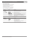
5 6 5 6
Figure 3.2 LBB 4512/00 High Power Radiator (Front view)
Note: The indicator LEDs are positioned
behind the semi-transparent cover and
are only visible when ON.