


INTEGRUS | Installation and User Instructions | System description and planning en | 8
Bosch Security Systems | 2005-04 | 3122 475 22015en
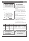
Guaranteed rectangular footprints can also be calculat-
ed with the footprint calculation tool (available on the
documentation CD-ROM). The given values are for
one radiator only, and therefore do not take into con-
sideration the beneficial effects of overlapping foot-
prints. The beneficial effects of reflections are also not
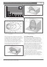
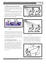
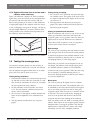
included. As rule of thumb can be given for systems
with up to 4 carriers, that if the receiver can pick up
the signal of two adjacent radiators the distance
between these radiators can be increased by a factor
1.4 approximately (see figure 1.22).
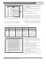
1.4.2 Planning radiators
Use the following procedure to plan the radiators:
1. Follow the recommendations in section 1.3 in order
to determine the positioning of the radiators.
2. Look up (in the table) or calculate (with the foot-
print calculation tool) the applicable rectangular
footprints.
3. Draw the rectangular footprints in the lay-out of the
room.
4. If the receiver can pick up the signal of two adja-
cent radiators in some areas, determine the overlap
effect and draw the footprint enlargement(s) in the
lay-out of the room.
5. Check whether you have sufficient coverage with
the radiators at the intended positions.
6. If not so, add additional radiators to the room.
See figure 1.15, figure 1.16 and figure 1.17 for examples
of a radiator lay out.
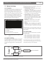
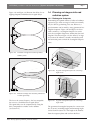
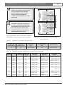
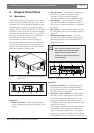
1.4.3 Cabling
Signal delay differences can occur due to differences in
the cable length from the transmitter to each radiator.
In order to minimize the risk of black spots, use equal
cable length from transmitter to radiator if possible (see
figure 1.23).
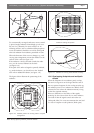
When radiators are loop-through connected, the
cabling between each radiator and the transmitter
should be as symmetrical as possible (see figure 1.24
and figure 1.25). The differences in cable signal delays
can be compensated with the signal delay compensa-
tion switches on the radiators.
Figure 1.22 The effect of overlapping footprints
L
R1 R2
R3 R4
R1 R2
R3 R4
W
1.4 W
1.4 L
Figure 1.23 Radiators with equal cable length
50m
50m
50m
50m
Figure 1.24 Asymmetrical arrangement of radiator
cabling (to be avoided)
Figure 1.25 Symmetrical arrangement of radiator cabling
(recommended)