


CY7C67200
Document #: 38-08014 Rev. *G Page 14 of 78
Halt Enable (Bit 0)
Setting this bit to ‘1’ immediately initiates HALT mode. While
in HALT mode, only the CPU is stopped. The internal clock still
runs and all peripherals still operate, including the USB
engines. The power savings using HALT in most cases will be
minimal, but in applications that are very CPU intensive the
incremental savings may provide some benefit.
The HALT state is exited when any enabled interrupt is
triggered. Upon exiting the HALT state, one or two instructions
immediately following the HALT instruction may be executed
before the waking interrupt is serviced (you may want to follow
the HALT instruction with two NOPs).
1: Enable Halt Mode
0: No Function
Reserved
All reserved bits must be written as ‘0’.
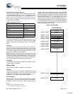
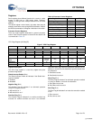
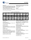
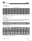
Interrupt Enable Register [0xC00E] [R/W]
Figure 12. Interrupt Enable Register
Register Description
The Interrupt Enable Register allows control of the hardware
interrupt vectors.
OTG Interrupt Enable (Bit 12)
The OTG Interrupt Enable bit enables or disables the OTG
ID/OTG4.4V Valid hardware interrupt.
1: Enable OTG interrupt
0: Disable OTG interrupt
SPI Interrupt Enable (Bit 11)
The SPI Interrupt Enable bit enables or disables the following
three SPI hardware interrupts: SPI TX, SPI RX, and SPI DMA
Block Done.
1: Enable SPI interrupt
0: Disable SPI interrupt
Host/Device 2 Interrupt Enable (Bit 9)
The Host/Device 2 Interrupt Enable bit enables or disables all
of the following Host/Device 2 hardware interrupts: Host 2
USB Done, Host 2 USB SOF/EOP, Host 2
WakeUp/Insert/Remove, Device 2 Reset, Device 2 SOF/EOP
or WakeUp from USB, Device 2 Endpoint n.
1: Enable Host 2 and Device 2 interrupt
0: Disable Host 2 and Device 2 interrupt
Host/Device 1 Interrupt Enable (Bit 8)
The Host/Device 1 Interrupt Enable bit enables or disables all
of the following Host/Device 1 hardware interrupts: Host 1
USB Done, Host 1 USB SOF/EOP, Host 1
WakeUp/Insert/Remove, Device 1 Reset, Device 1 SOF/EOP
or WakeUp from USB, Device 1 Endpoint n.
1: Enable Host 1 and Device 1 interrupt
0: Disable Host 1 and Device 1 interrupt
HSS Interrupt Enable (Bit 7)
The HSS Interrupt Enable bit enables or disables the following
High-speed Serial Interface hardware interrupts: HSS Block
Done, and HSS RX Full.
1: Enable HSS interrupt
0: Disable HSS interrupt
In Mailbox Interrupt Enable (Bit 6)
The In Mailbox Interrupt Enable bit enables or disables the
HPI: Incoming Mailbox hardware interrupt.
1: Enable MBXI interrupt
0: Disable MBXI interrupt
Out Mailbox Interrupt Enable (Bit 5)
The Out Mailbox Interrupt Enable bit enables or disables the
HPI: Outgoing Mailbox hardware interrupt.
1: Enable MBXO interrupt
0: Disable MBXO interrupt
Bit # 15 14 13 12 11 10 9 8
Field
Reserved OTG
Interrupt
Enable
SPI
Interrupt
Enable
Reserved Host/Device 2
Interrupt
Enable
Host/Device 1
Interrupt
Enable
Read/Write - - - R/W R/W - R/W R/W
Default 0 0 0 0 0 0 0 0
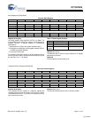
Bit # 7 6 5 4 3 2 1 0
Field
HSS
Interrupt
Enable
In Mailbox
Interrupt
Enable
Out Mailbox
Interrupt
Enable
Reserved UART
Interrupt
Enable
GPIO
Interrupt
Enable
Timer 1
Interrupt
Enable
Timer 0
Interrupt
Enable
Read/Write R/W R/W R/W - R/W R/W R/W R/W
Default 0 0 0 1 0 0 0 0
[+] Feedback